- Posted on
- • Camera repairs
Canon EOS R10 Beyond Repair: How Canon’s Design Blocks Fixes After Minor Failures
- Author
-
-

- User
- Photo-parts
- Posts by this author
- Posts by this author
-
The title of this post can’t possibly capture the full extent of frustration that comes with repairing modern Canon cameras. We’ve got everything here: serious damage from minor water ingress, excessive reliance on proprietary ICs, and complete unavailability of component-level spare parts. Things are so bad that if you try to Google the part number of the faulty chip, you’ll find exactly this page, plus maybe one more - also from my own site.
This Canon EOS R10 arrived with a straightforward backstory. It was bought for parts after "a little bit of water damage", with the idea of repairing and reselling it (not by me). However, the "simple repair" didn't pan out, and I received it with the diagnosis: "won't turn on" So let's disassemble it and dig deep into the circuitry of Canon's latest-generation mirrorless models.
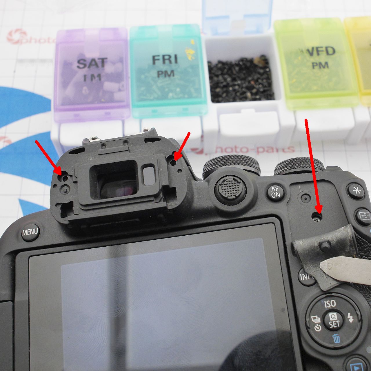
The camera was partially disassembled when it arrived, so the disassembly process is shown only where it's possible. To remove the rear panel with the screen, start by taking out all screws shown below:
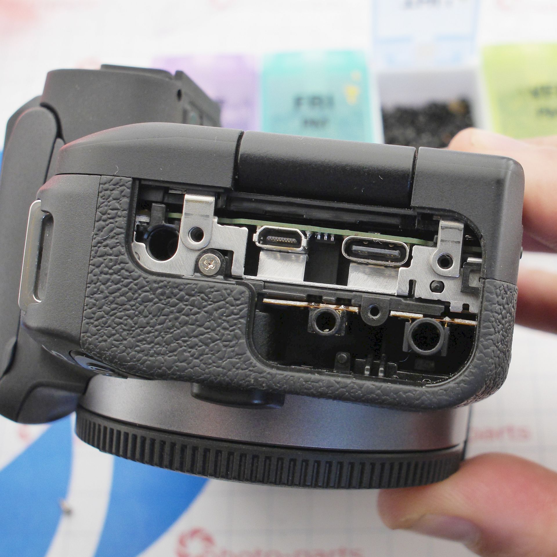
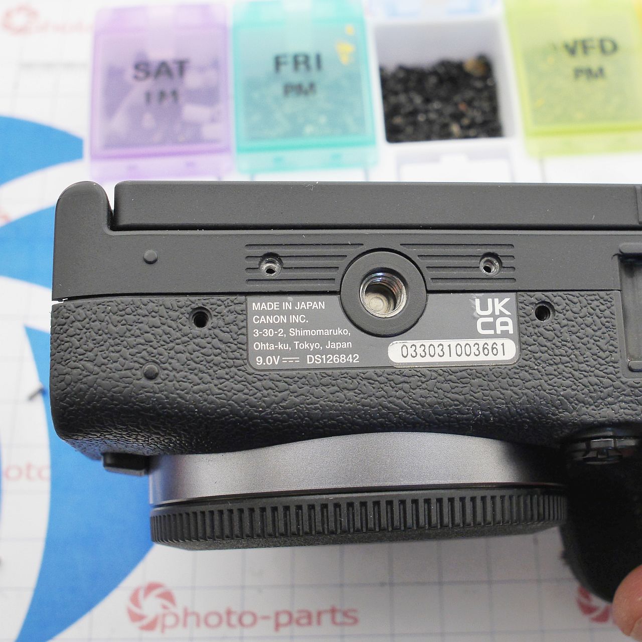
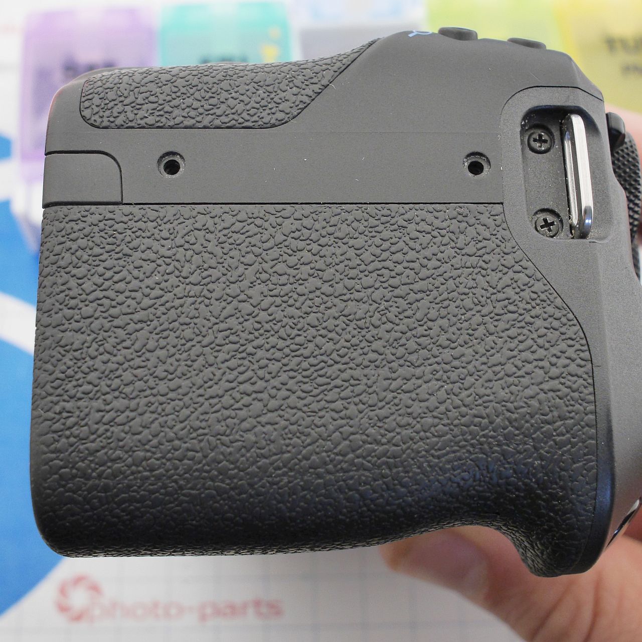
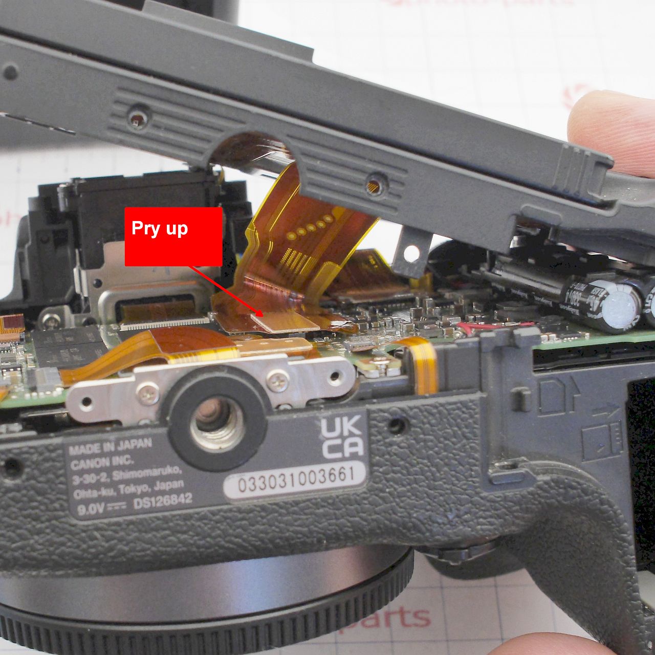
Disconnect the rear panel connector before lifting the panel off completely:
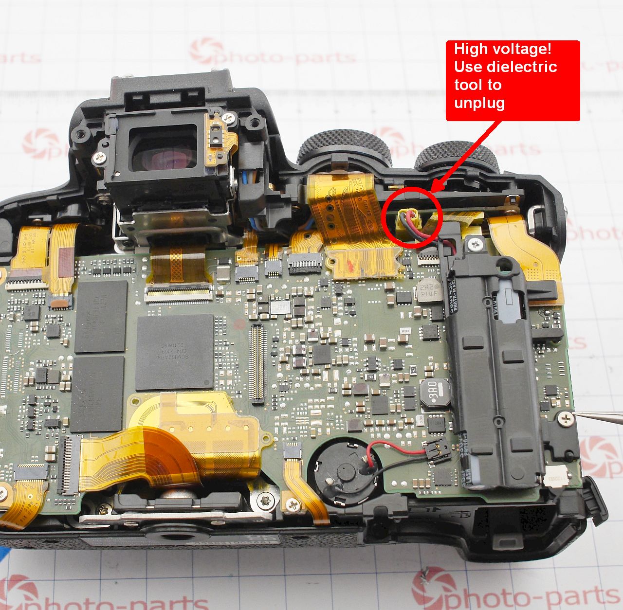
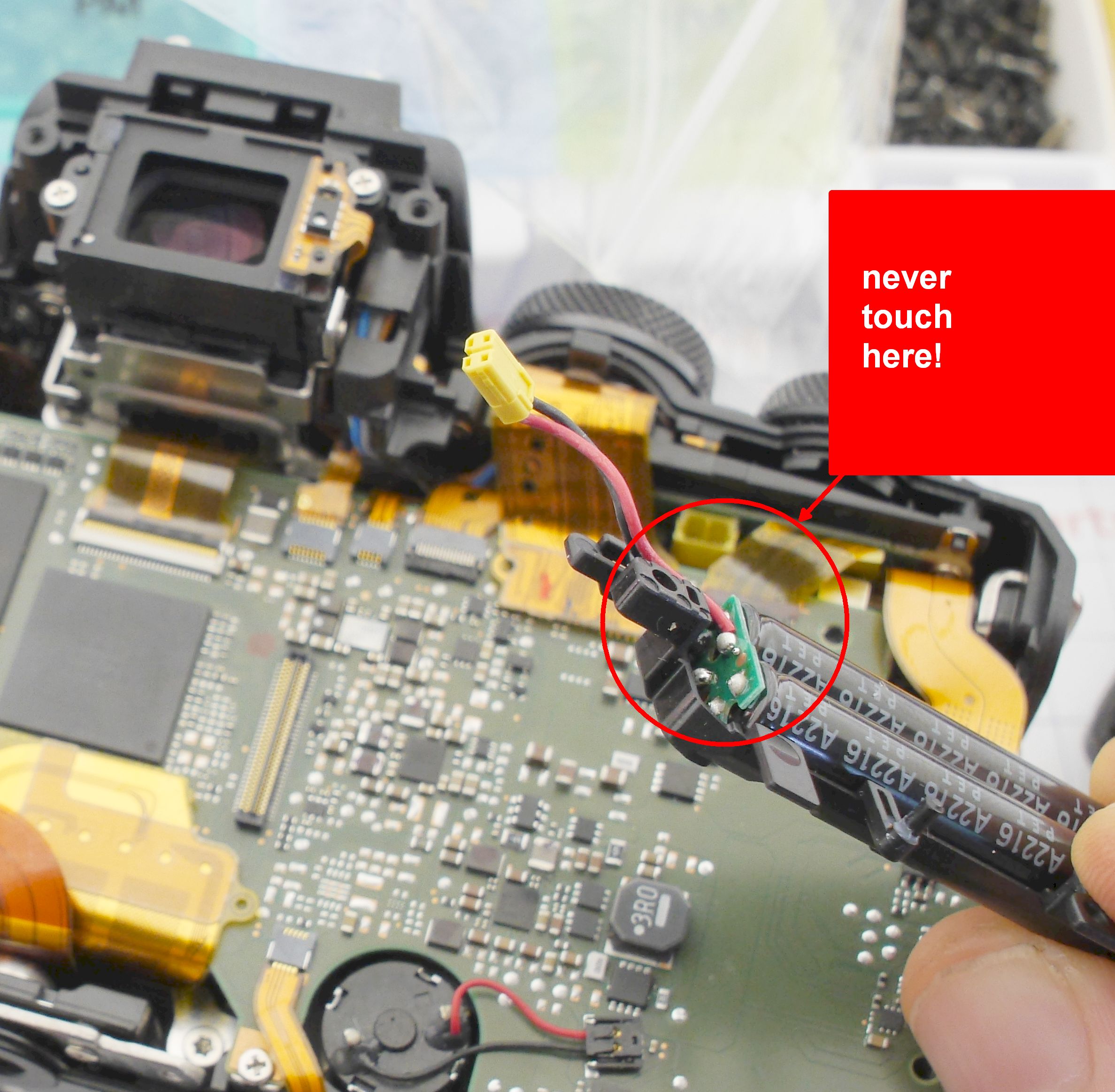
Important! The camera has a built-in flash, which means it also has a charged high-voltage capacitor - potentially at 300V. The first thing you must do is disconnect the flash capacitor from the board using a non-conductive tool to avoid shocking yourself or shorting the board. Then, remove the capacitor block and avoid touching its exposed terminals.
To access the mainboard fully, remove the top panel. The necessary screws are shown below; one is deep inside the battery compartment:
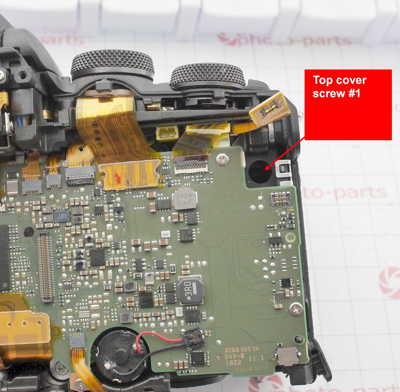
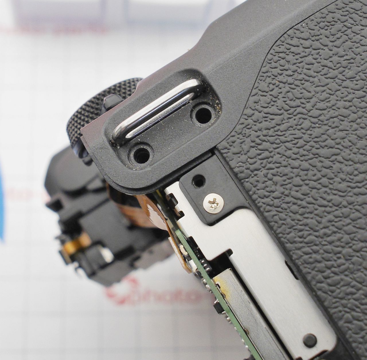
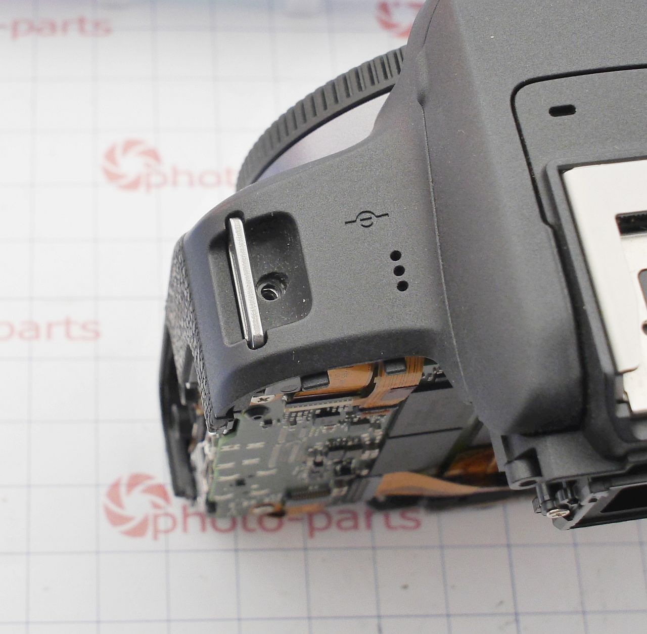
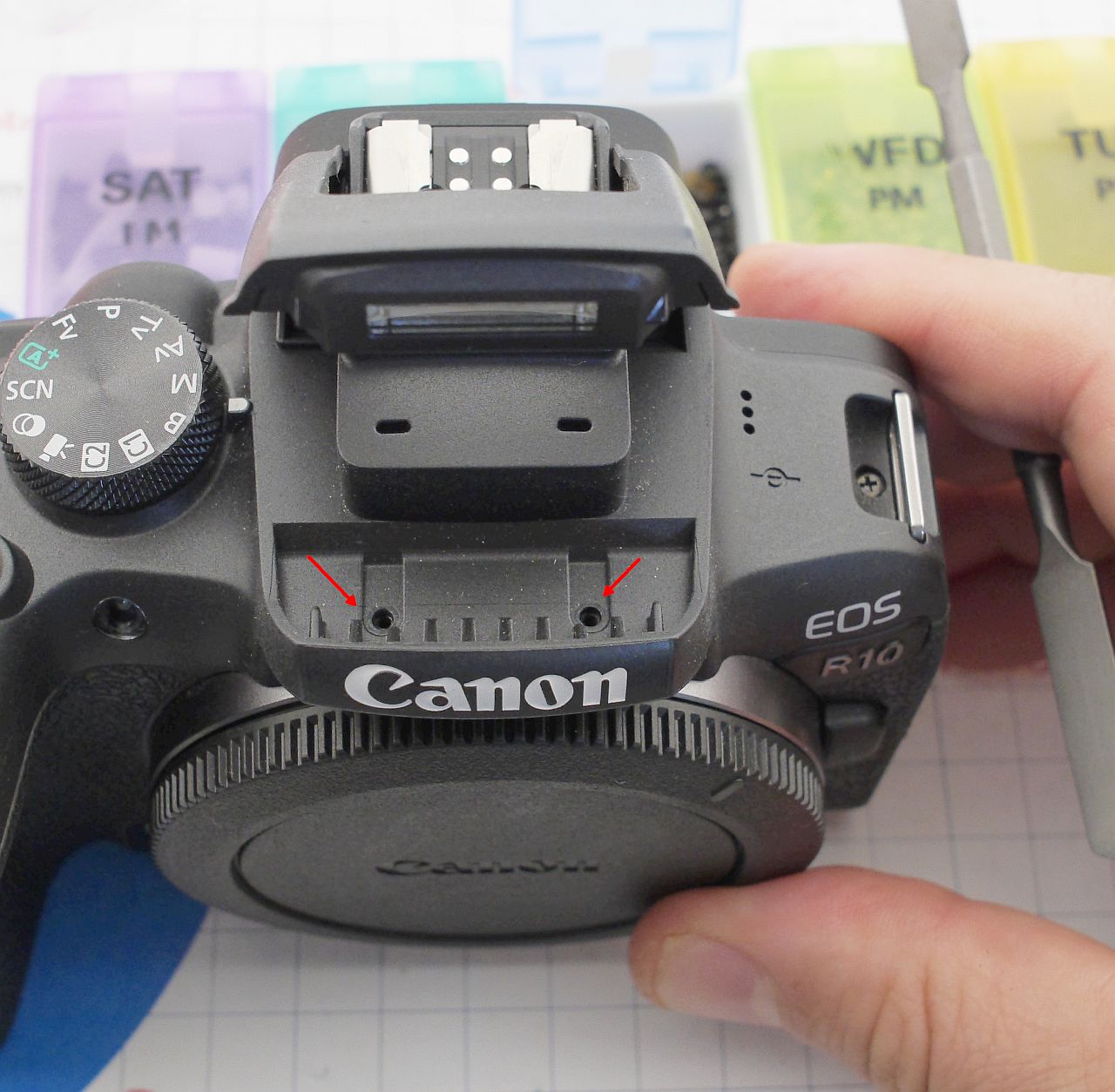
Disconnect the following connectors:
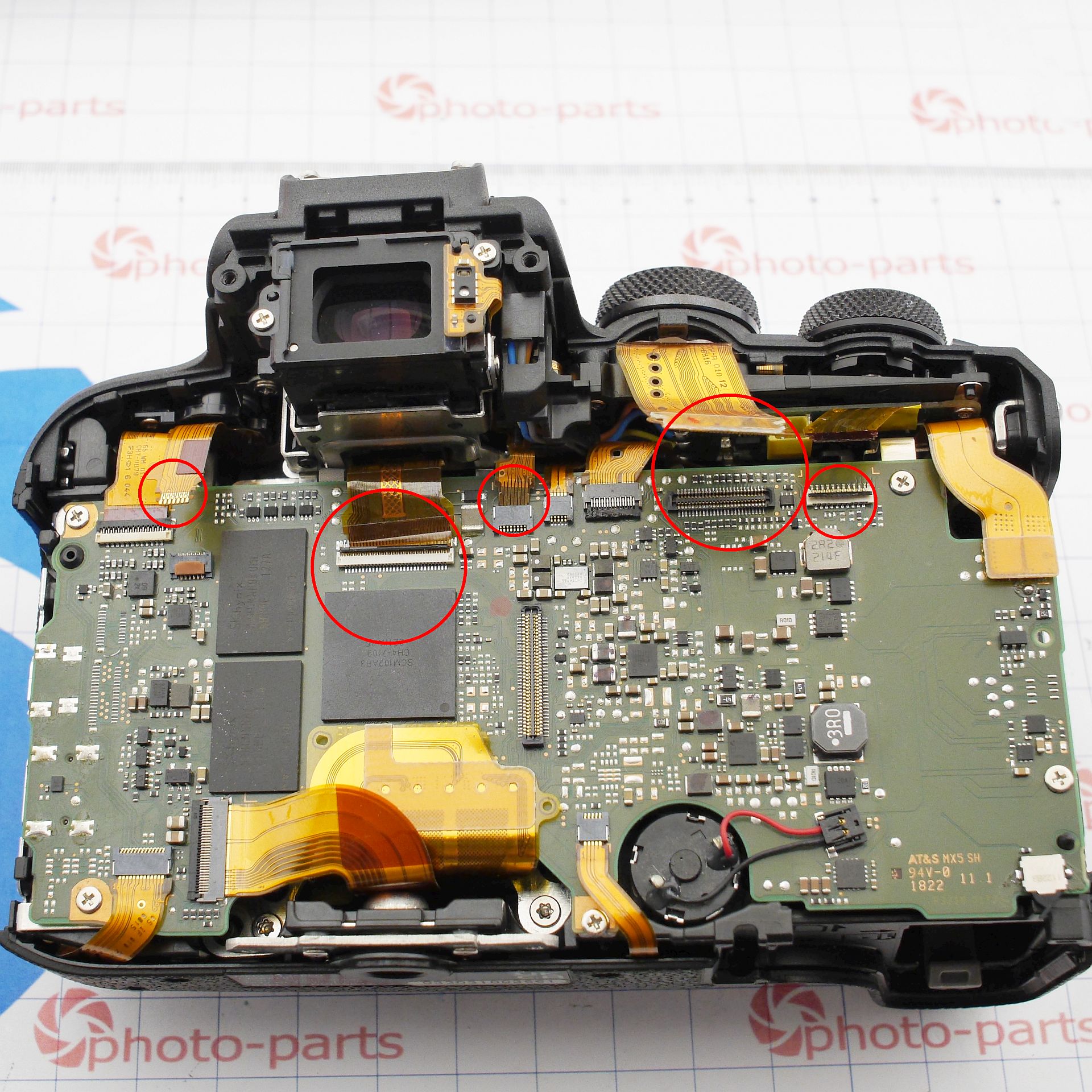
After that, the mainboard comes off easily - just unplug a few more flex cables:
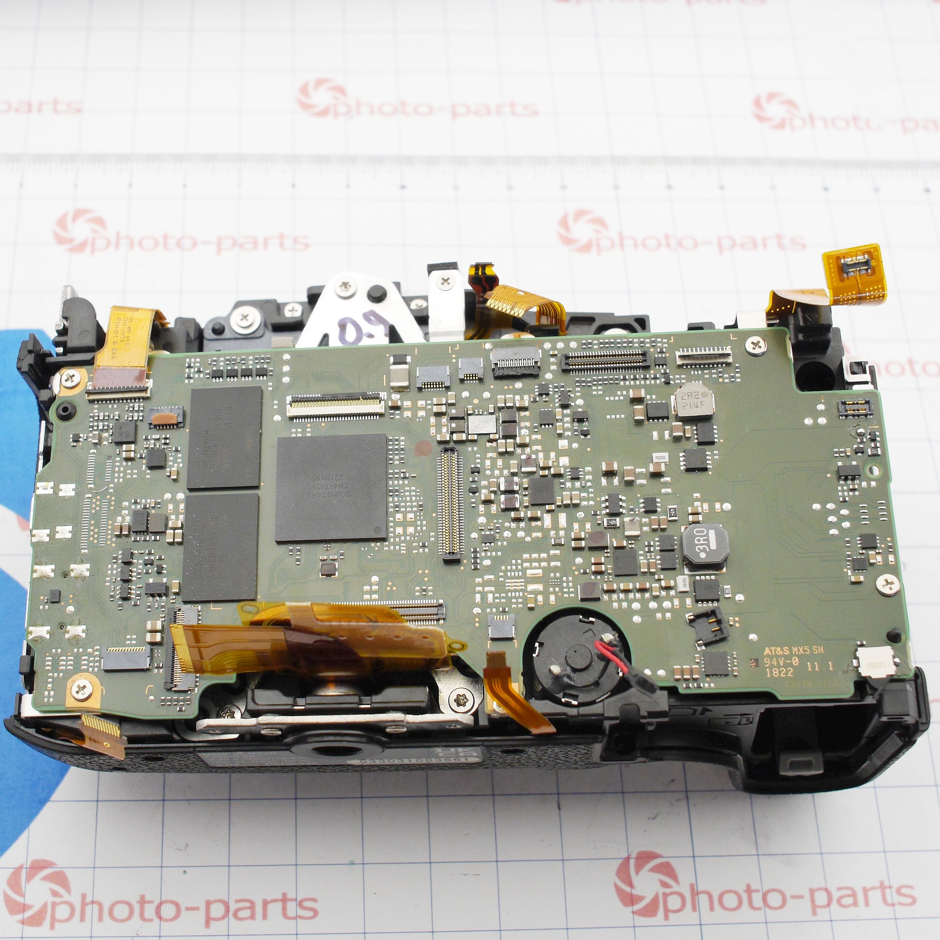
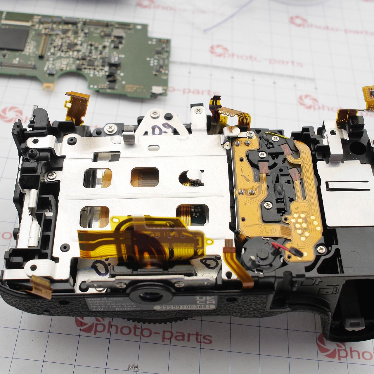
A quick side note: out of curiosity, I removed the shutter unit (not something you should do unless necessary - the sensor sits on spring-loaded calibration posts, and removing the shutter disrupts alignment). The shutter was somewhat surprising. Even though this is a crop-sensor camera, the shutter mechanism is full-frame-sized. The shutter curtains appear to span the entire mechanism; the opening is small on the lens side, large on the sensor side. Some components are missing near the shutter arms - makes me wonder what they’re for, which model they're used on, and why they're absent here.
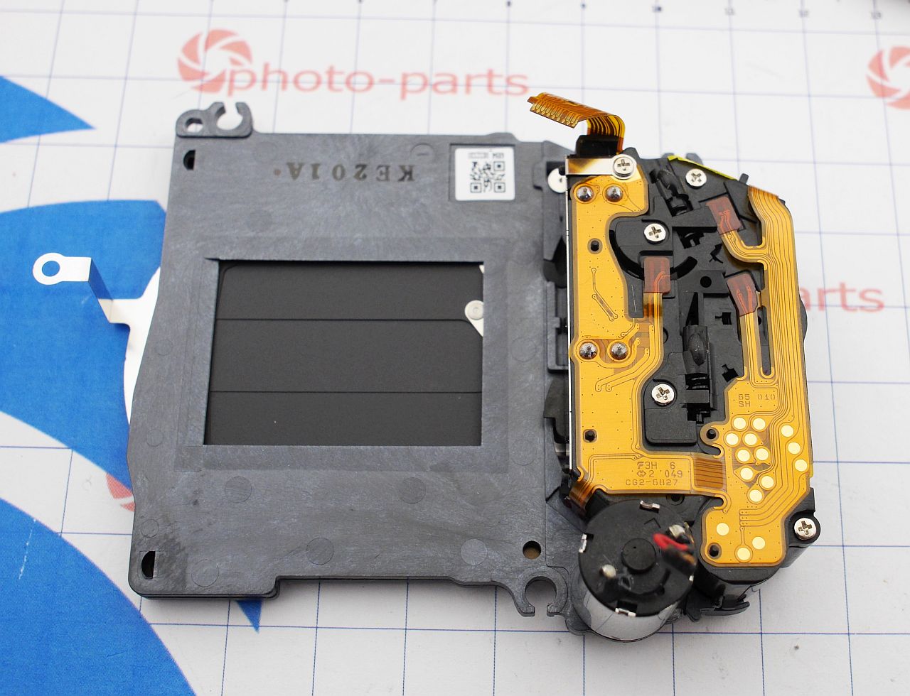
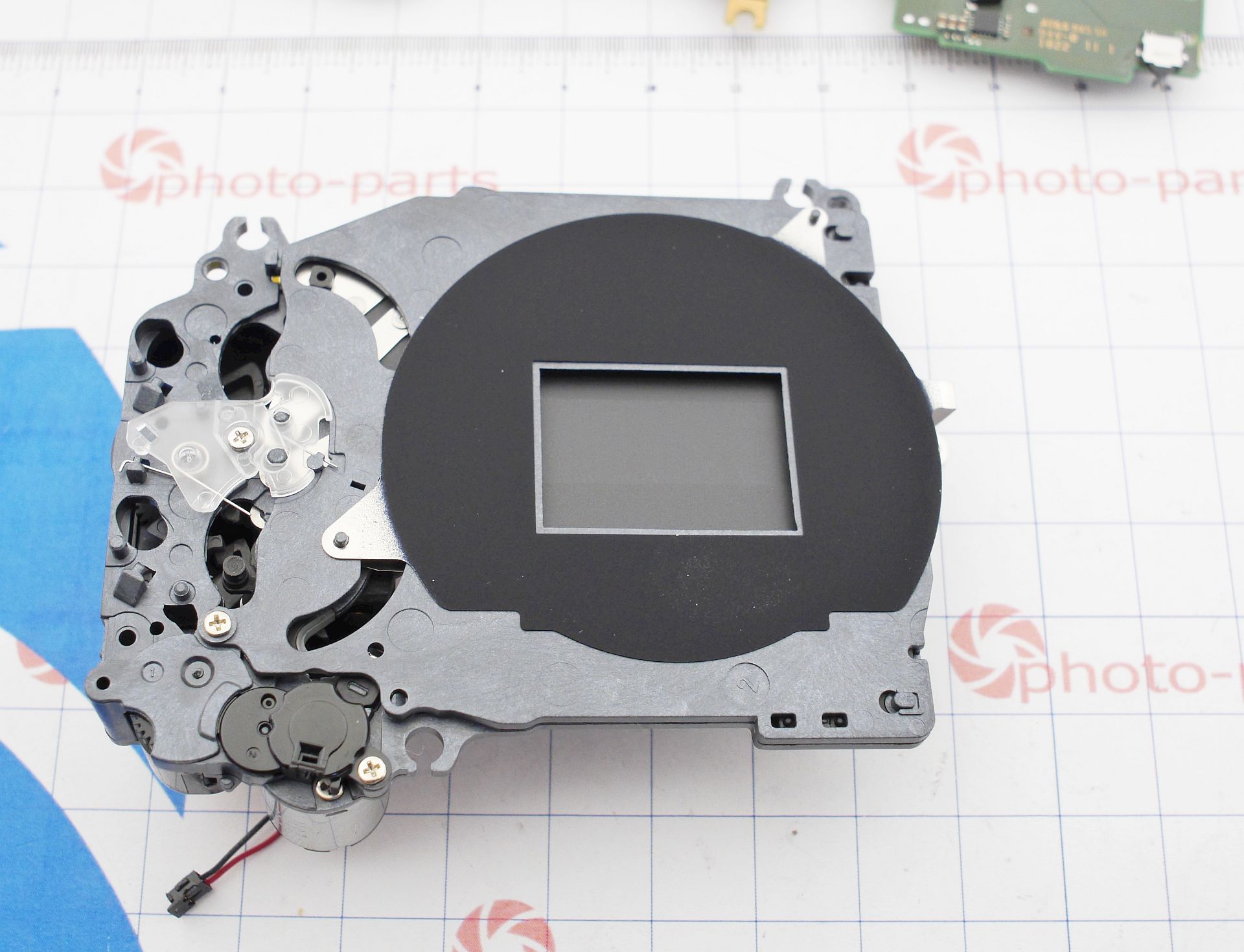
But the goal here wasn't to study mechanicals - let's get back to the mainboard repair.
At first glance, I found no catastrophic liquid damage. Most likely, the board had already been cleaned. I didn't find corroded traces or oxidized pins either, so I'll assume the moisture exposure was very localized. If you'd like to examine the board photos in detail, they're available here: Canon EOS R10 PCB photo gallery.
The first step in any "won't power on" diagnosis is to connect the bare board to a lab power supply. An experienced eye can learn a lot just from current draw. Some obvious cases:
- High current draw: something is overheating.
- No current draw: check for broken traces or blown fuses.
- Small, constant draw: system can't boot, stuck in a loop.
- Quick spike followed by drop: classic symptom of a shorted secondary power rail triggering protection.
In this case, I observed the last scenario. So I began probing for shorts across large capacitors. But modern digital systems are tricky - CPU cores can show very low resistance even when healthy. Where 10-year-old cameras showed "infinite" resistance on power rails, modern ones are normal at 5–30 ohms. In the GPU world, this is even closer to short circuit territory.
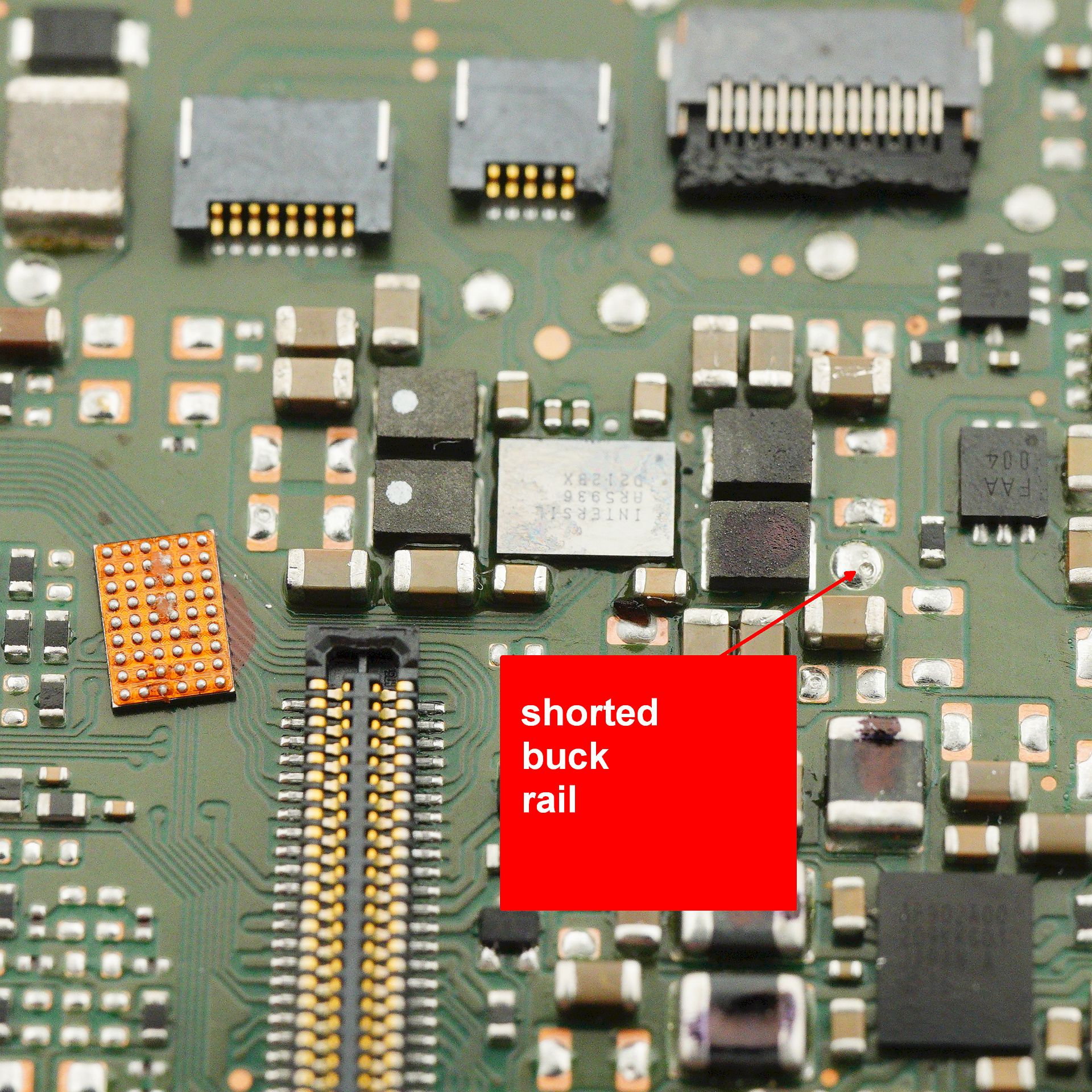
Eventually, I traced a real short to a single power rail of an IC:

And here's where the problems began. The chip was clearly marked "INTERSIL AR5936" - but absolutely no datasheets, purchase links, or ads exist for it. Just two links showed up: a dead-end forum post and a listing on my own site.

All my repair tech contacts - freelancers, authorized service folks, even Chinese chip distributors - came up empty. It turns out this chip is used only in modern Canon mirrorless cameras and nowhere else.
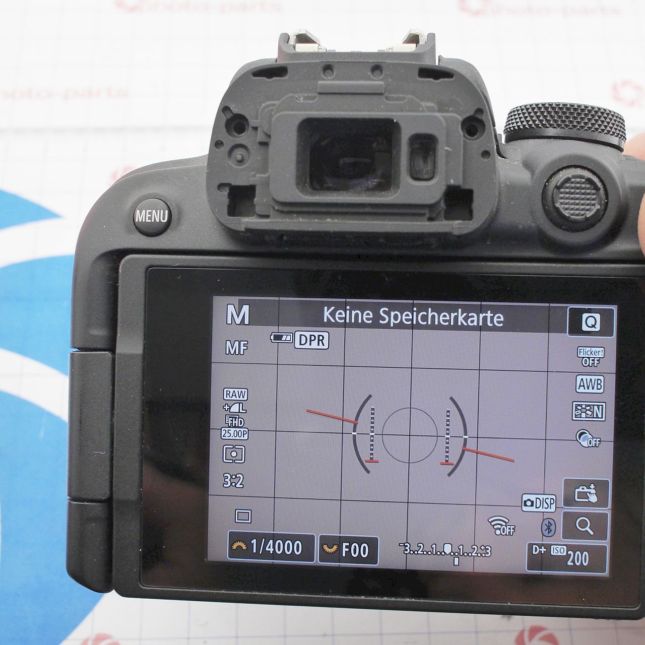
After a long wait, I finally salvaged a working AR5936 from a Canon R6 Mark II donor board. And after swapping it in - the camera powered on!
This could've been the end of the story, if not for the broader pattern of Canon mirrorless failures. Since my R10 was now functional, I decided to document the power architecture by mapping key voltage rails. Modern cameras use a ton of DC-DC converters - sometimes dozens. This makes sense: instead of one high-current central supply with thick traces, multiple small local converters are more space-efficient, cooler, and cleaner electrically.
I counted at least 13 power rails, most of them generated by custom ICs that are unavailable for purchase.
Here are the key chips:
- Dialog DA6101: Main power controller from battery voltage. It generates mid-level secondaries (3.3V, 5V, 4V). It's usually the first to burn if the battery line receives an overvoltage (which often happens when using dummy batteries).
- AP902A00: Another custom chip, manufacturer unknown. It converts mid-range voltages to very low core voltages (1.2V and 0.8V) for the CPU. It typically fails together with the Dialog chip.
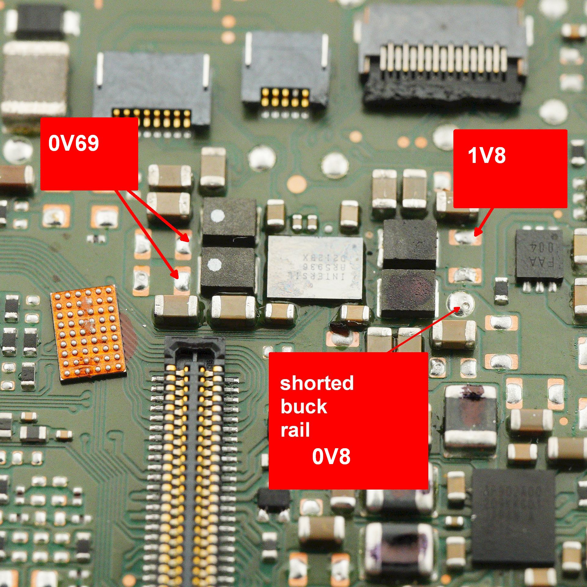
- INTERSIL AR5936: The hero (or villain) of this story. Generates 0.69V, 0.8V, and 1.8V rails, also for the CPU. In my case, the 0.8V rail was shorted.
Some data exists for Dialog DA6101's successor:
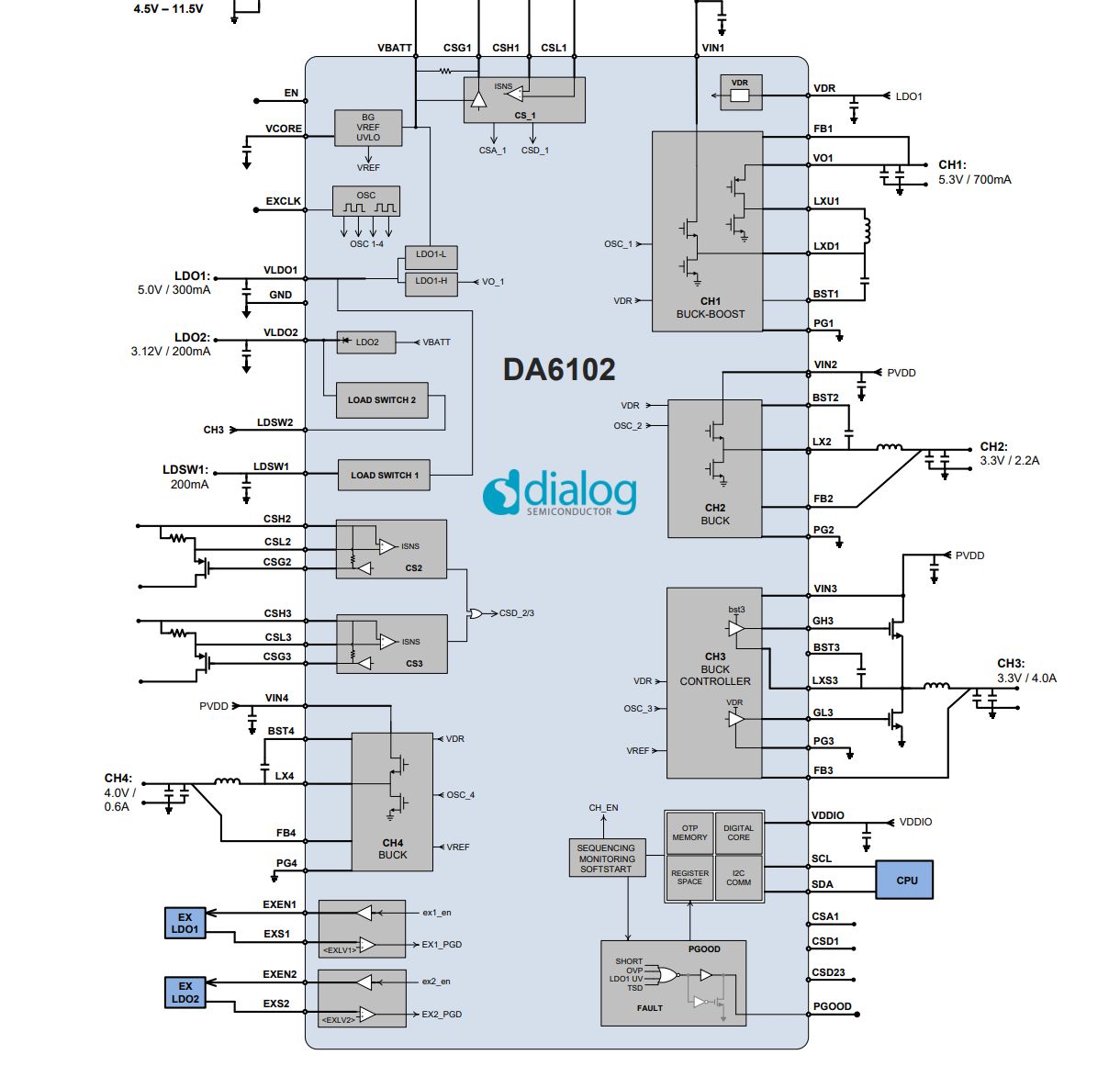
The actual voltage output from DA6101 may differ, likely because it's a programmable IC and controlled by firmware:
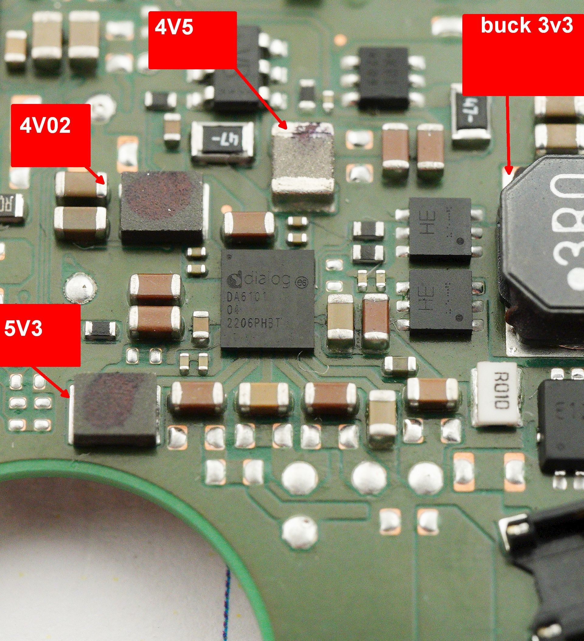
This is concerning - because the chip uses one-time programmable memory for setting initial voltages and even I2C addresses. It's possible that replacing the chip won't be enough - you might need the original configuration as well.
Voltage map for AP902A00 is shown below. You'll notice that the 0.8V rail uses a dual-phase design (two inductors joined at a common node):
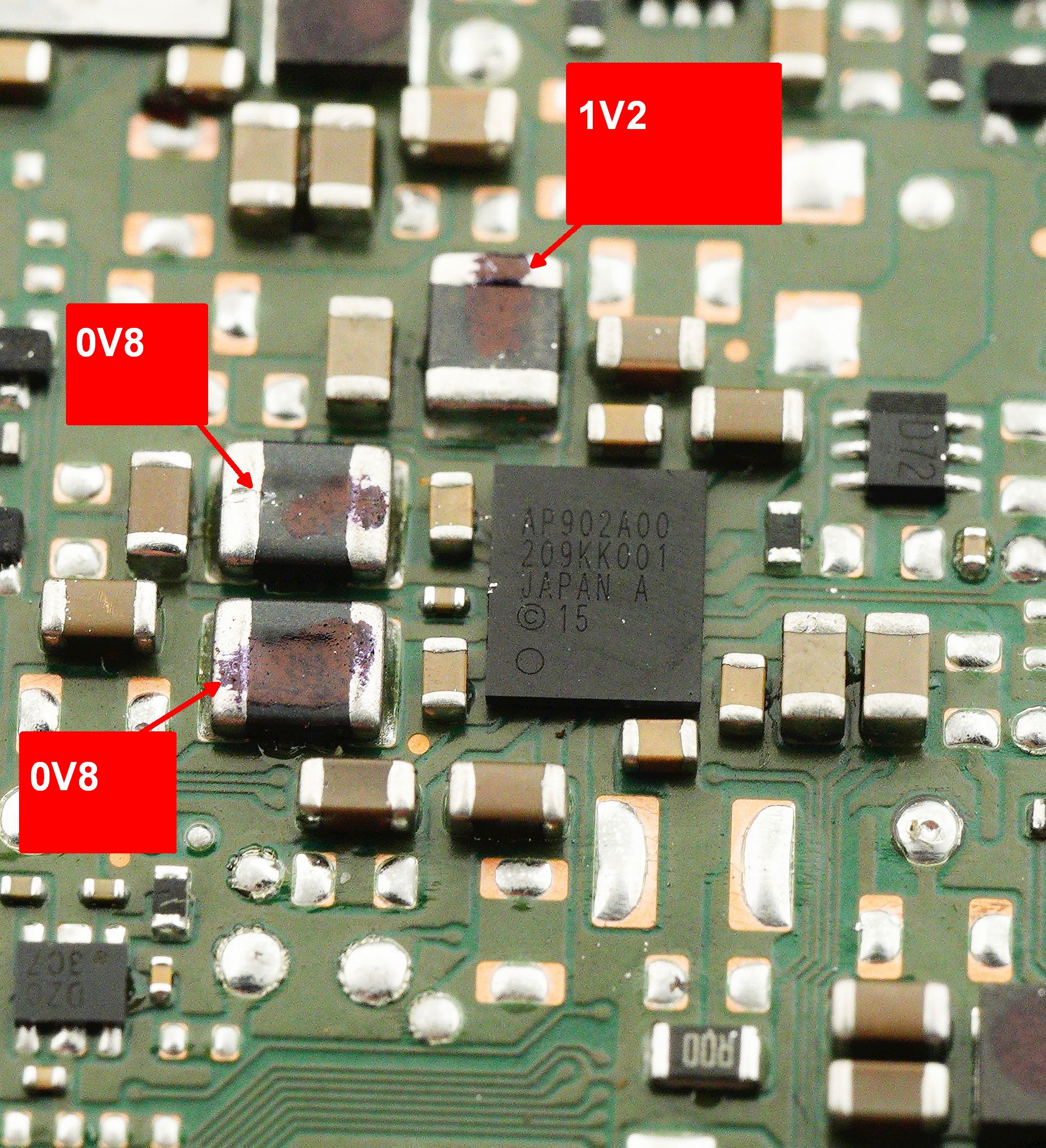
And here's the voltage map for INTERSIL AR5936 - same story with dual-phase rail for 0.69V:
There may be no moral to this story. The repair was ultimately successful. But all the skill, experience, and diagnostics mean little when spare parts are locked behind a supply wall.
Add Comment
This policy contains information about your privacy. By posting, you are declaring that you understand this policy:
- Your name, rating, website address, town, country, state and comment will be publicly displayed if entered.
- Aside from the data entered into these form fields, other stored data about your comment will include:
- Your IP address (not displayed)
- The time/date of your submission (displayed)
- Your email address will not be shared. It is collected for only two reasons:
- Administrative purposes, should a need to contact you arise.
- To inform you of new comments, should you subscribe to receive notifications.
- A cookie may be set on your computer. This is used to remember your inputs. It will expire by itself.
This policy is subject to change at any time and without notice.
These terms and conditions contain rules about posting comments. By submitting a comment, you are declaring that you agree with these rules:
- Although the administrator will attempt to moderate comments, it is impossible for every comment to have been moderated at any given time.
- You acknowledge that all comments express the views and opinions of the original author and not those of the administrator.
- You agree not to post any material which is knowingly false, obscene, hateful, threatening, harassing or invasive of a person's privacy.
- The administrator has the right to edit, move or remove any comment for any reason and without notice.
Failure to comply with these rules may result in being banned from submitting further comments.
These terms and conditions are subject to change at any time and without notice.
Comments