- Posted on
- • Camera repairs
Canon EOS RP - ERR 06, An Almost Repair Story
- Author
-
-

- User
- Photo-parts
- Posts by this author
- Posts by this author
-
How often have you thought about the "ultrasonic sensor cleaning” technology that’s present in almost every modern camera? Probably not very often — after all, its work is barely noticeable, if not downright invisible. The idea is simple: when the camera powers off, the outer glass of the sensor filter vibrates at high frequency, shaking off dust (in theory). In practice, this technology is far from a cure-all - micro-vibrations of the glass do little against heavily charged dust, sticky particles, or fine droplets.
In short, nothing can replace a good manual sensor cleaning.
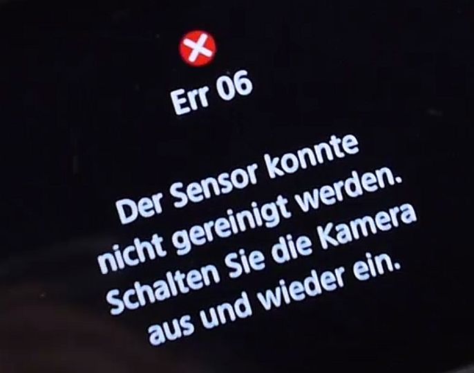
However, in Canon cameras, the health of the cleaning system is monitored, and if something goes wrong, the camera throws an annoying "ERR06". Usually, that's not even a reason to visit a repair shop - you can disable automatic cleaning in the menu and forget about it.
But this time I decided, no matter what, to find out what exactly can fail in the "dust shaker" system - and whether it can be repaired.
Spoiler: not everything went smoothly, but I did achieve some results.
My test subject - a Canon EOS RP showing err 06. This article covers the teardown, an attempt at full restoration, several failed experiments, and finally, a small "trick" to fool the camera electronics. As always - there's a short highlight video embedded below.
Disassembly
The camera's construction is quite simple - like in many other Canon mirrorless models (praise the engineers!). There are no hidden screws, one-way clips, or short ribbon cables, and the entire camera can be taken apart down to the last screw in about half an hour.
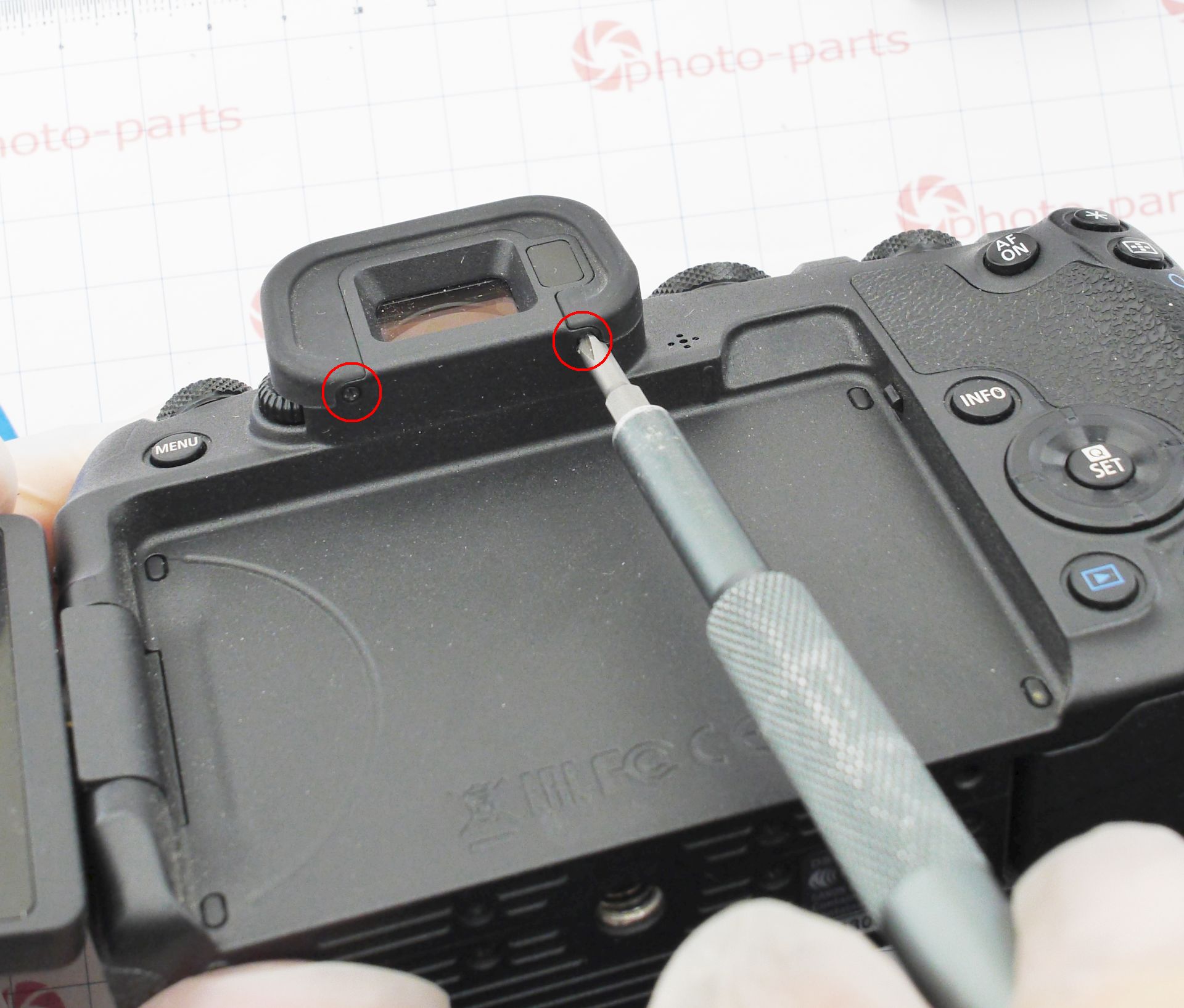
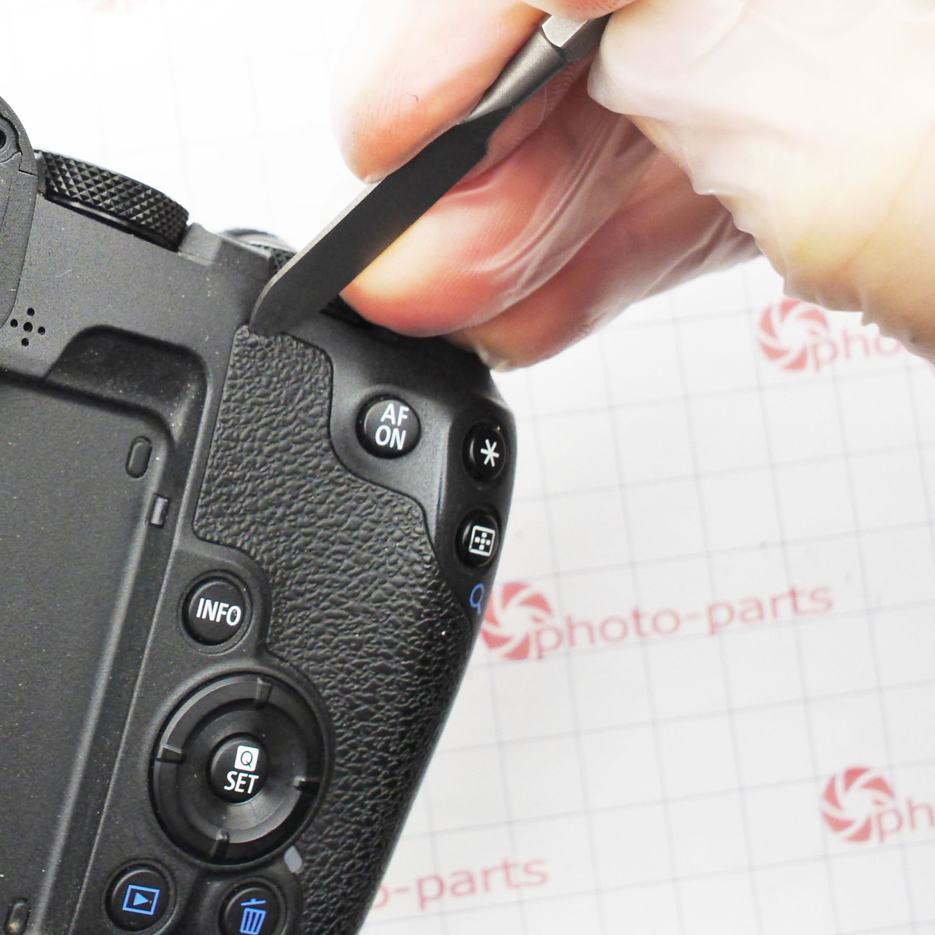
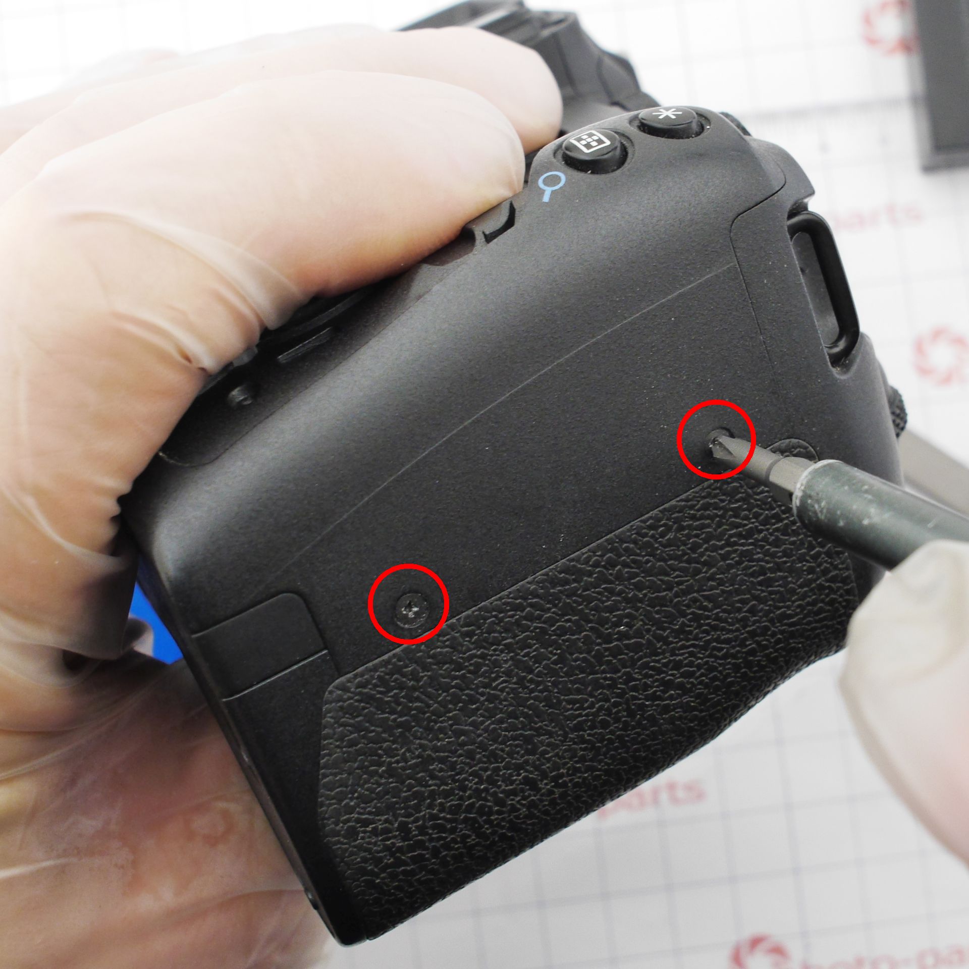
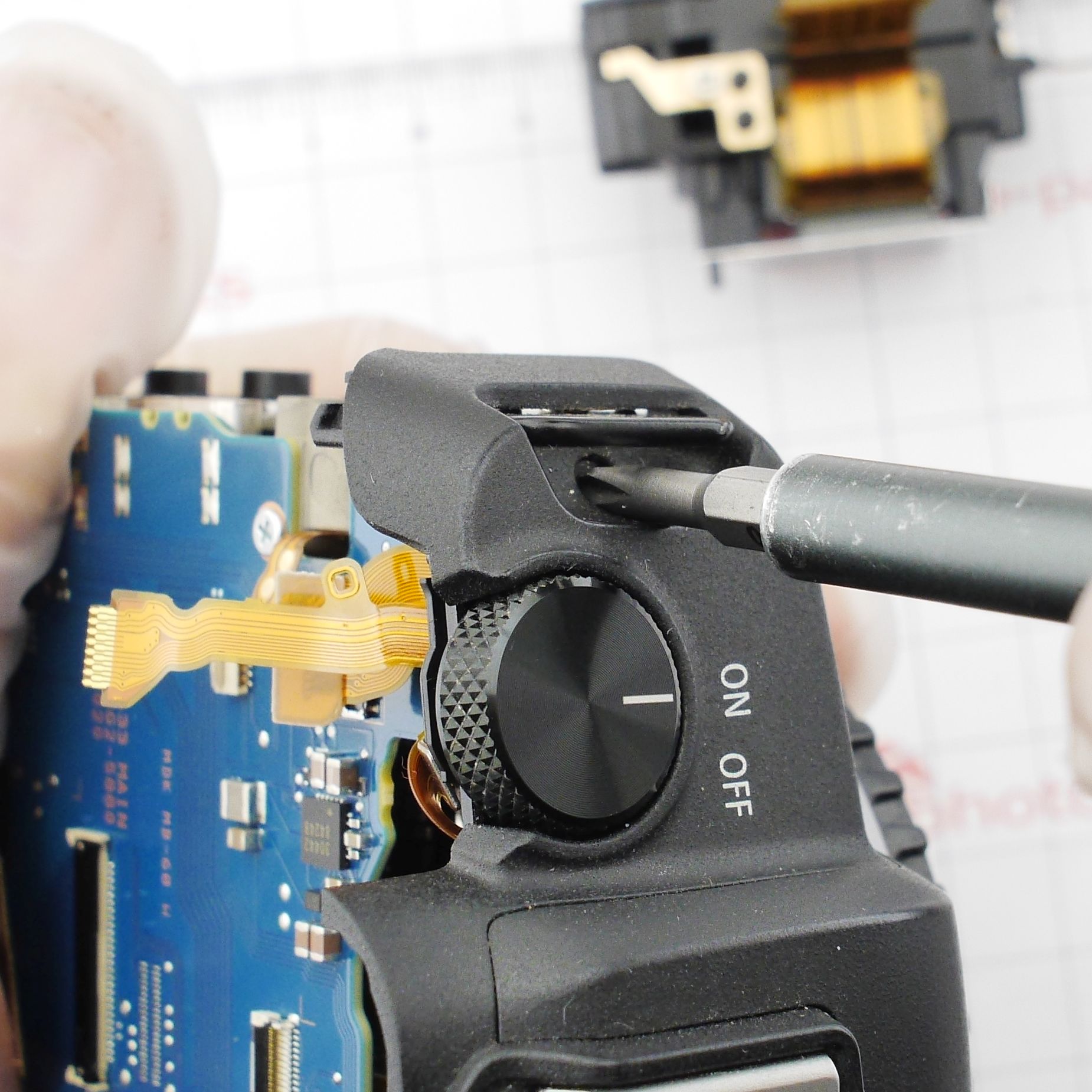
First, remove the viewfinder eyecup - it's held by two screws, and beneath it are four more. Then peel off the decorative rubber grips - the side and the rear thumb rest. Under each, there's a hidden screw:
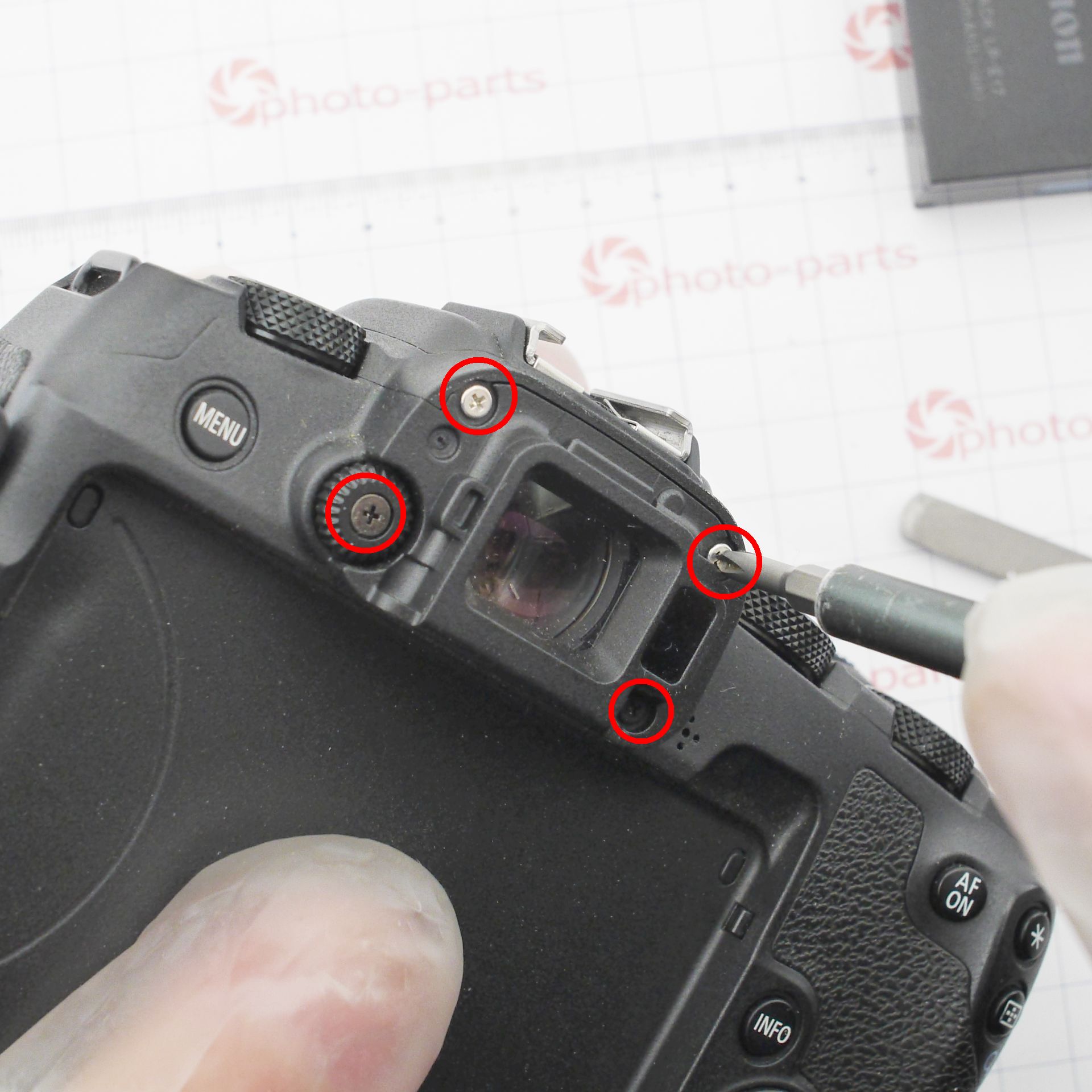
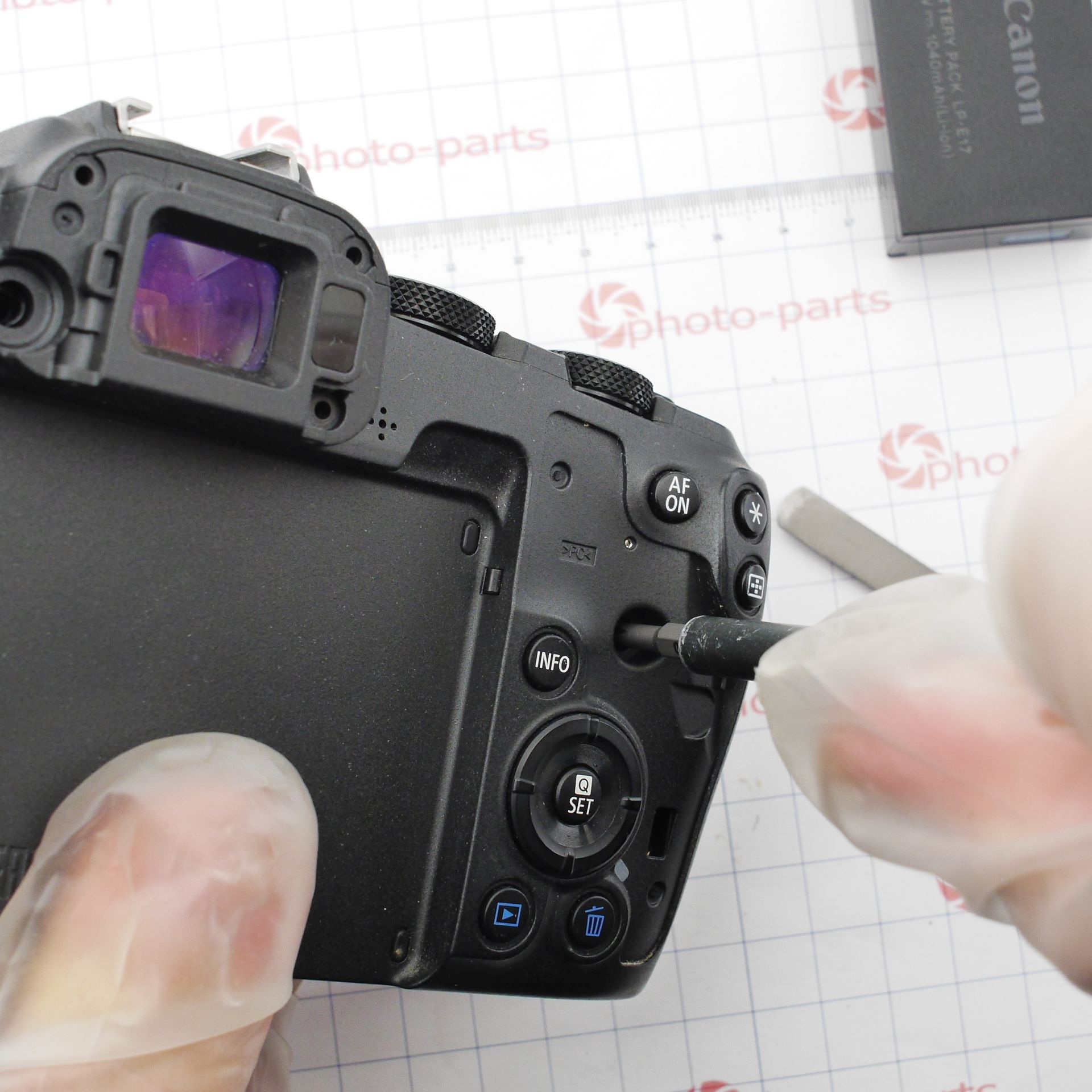
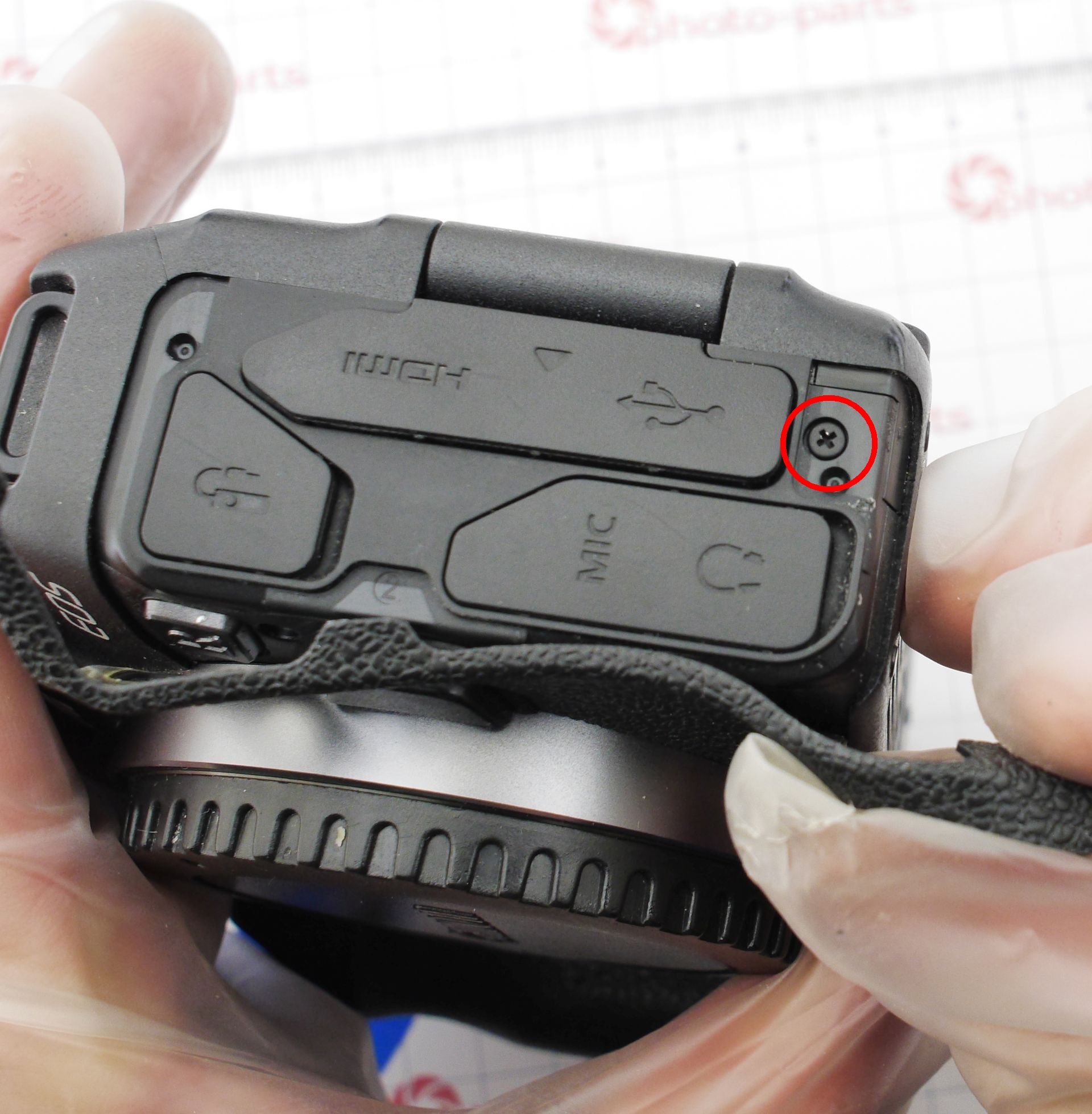
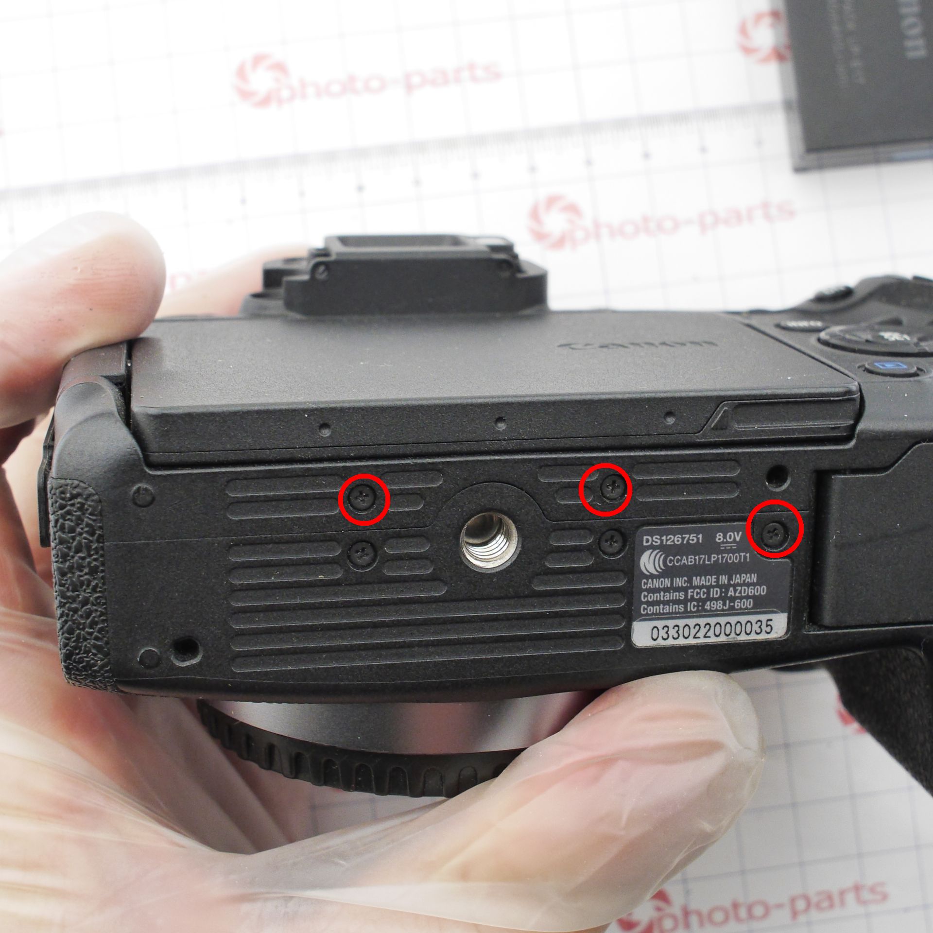
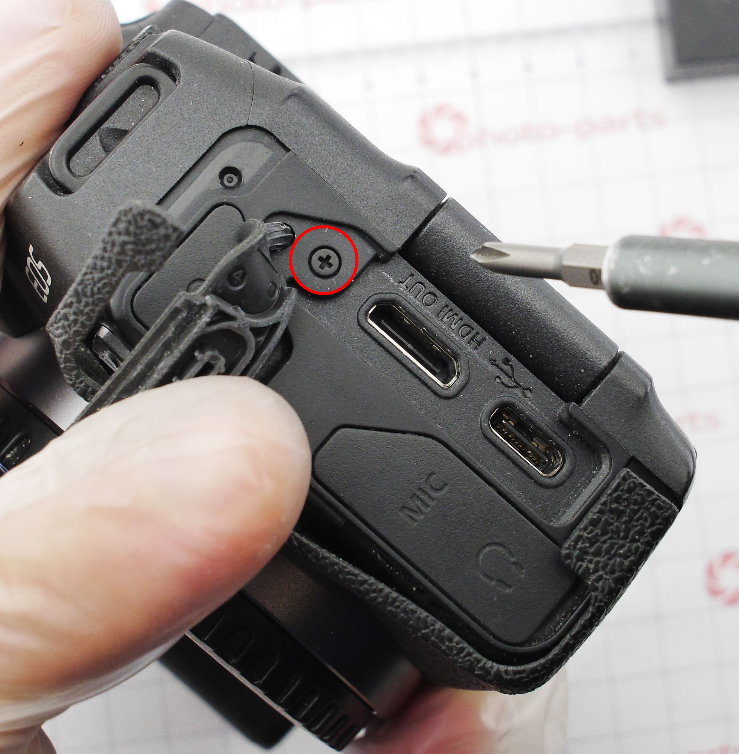
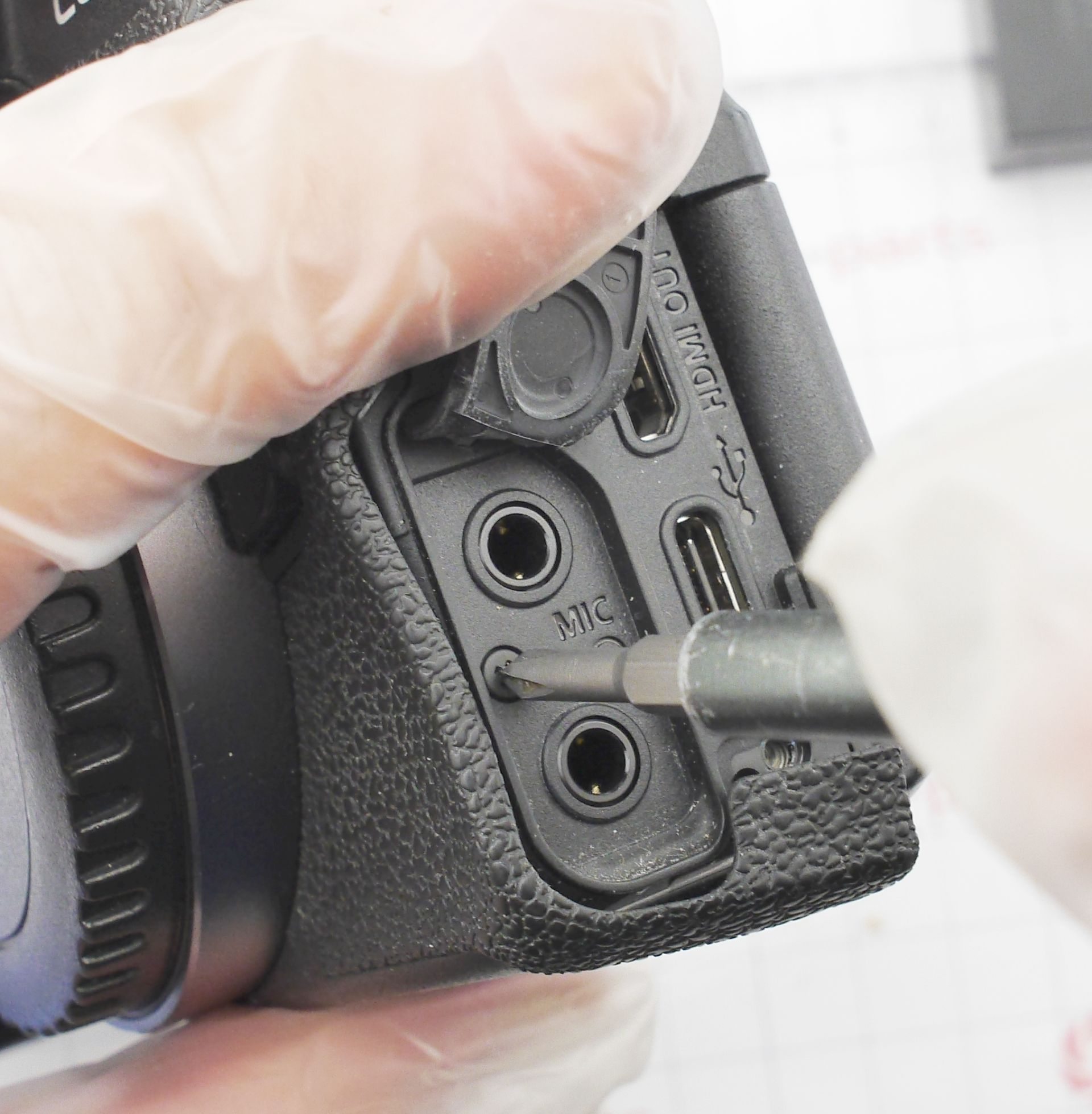
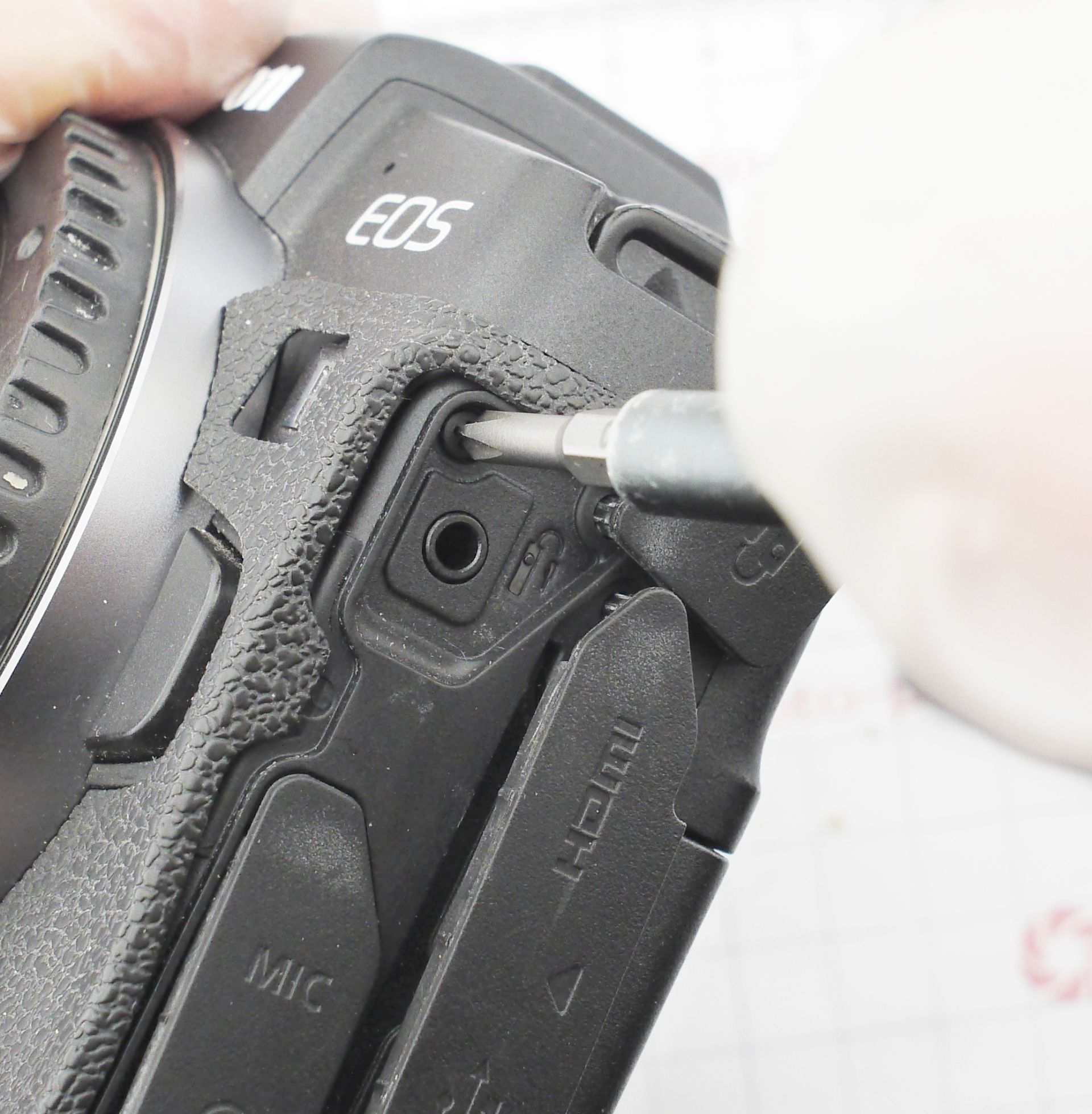
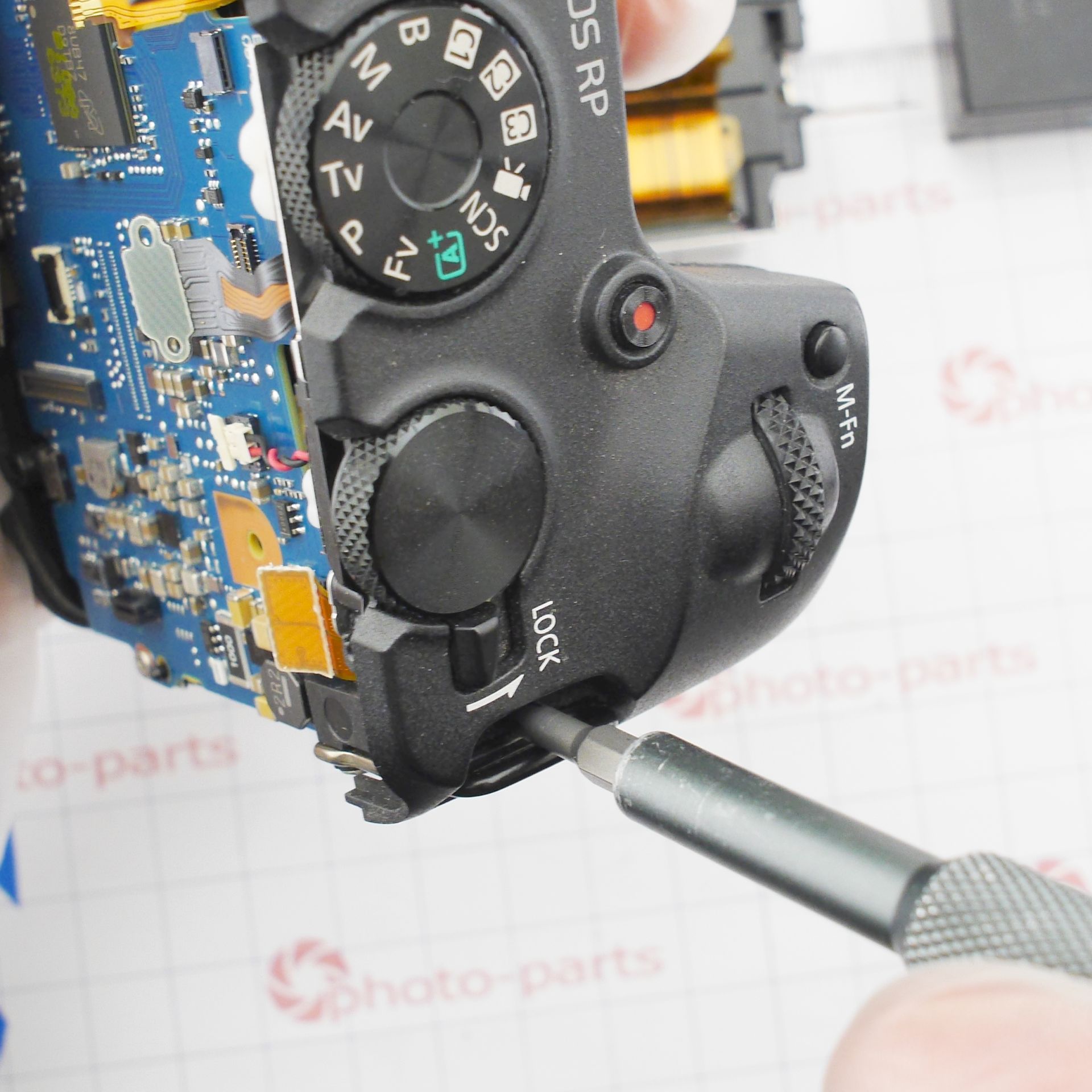
Next come the visible screws on the side panels: 2 on the right side, 3 on the bottom, and 3 more under the port covers for mic, headphones, and USB/HDMI.
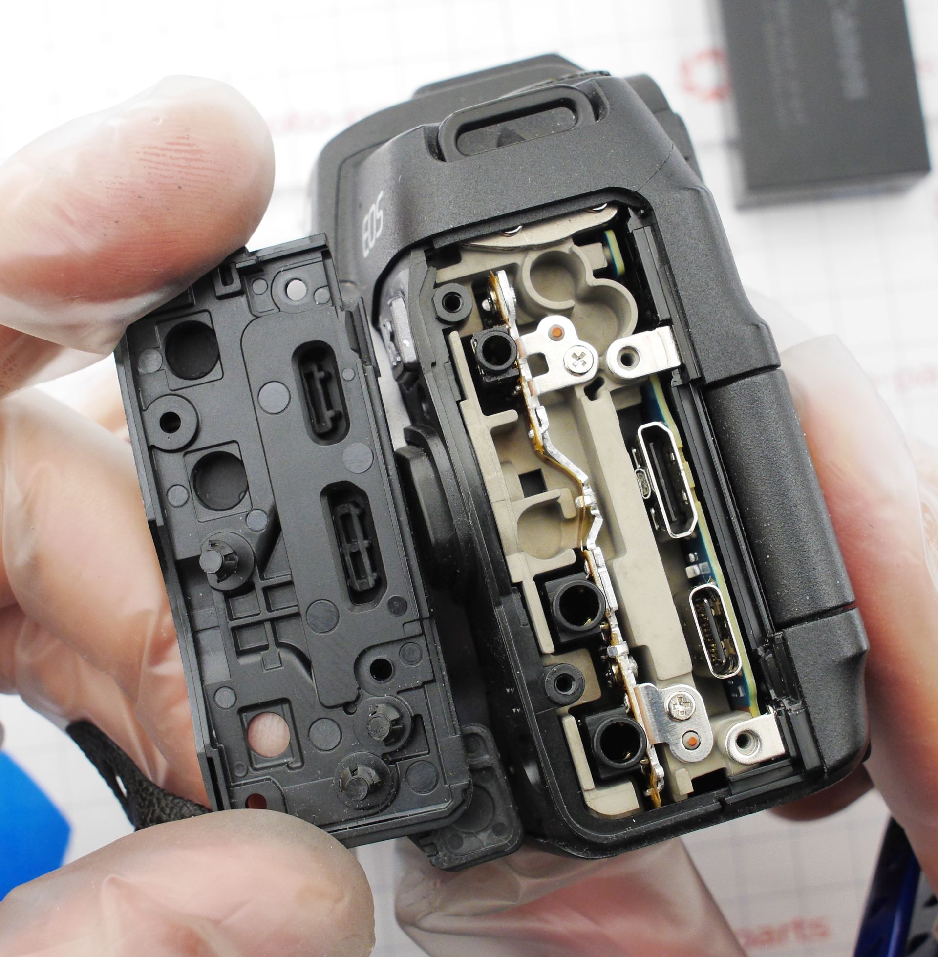
The side panel with the ports can now be removed and set aside. The back panel separates easily from the base, still connected by a long, comfortable ribbon cable to the main board. Gently lift and unclip the cable - it's held by a mezzanine connector.
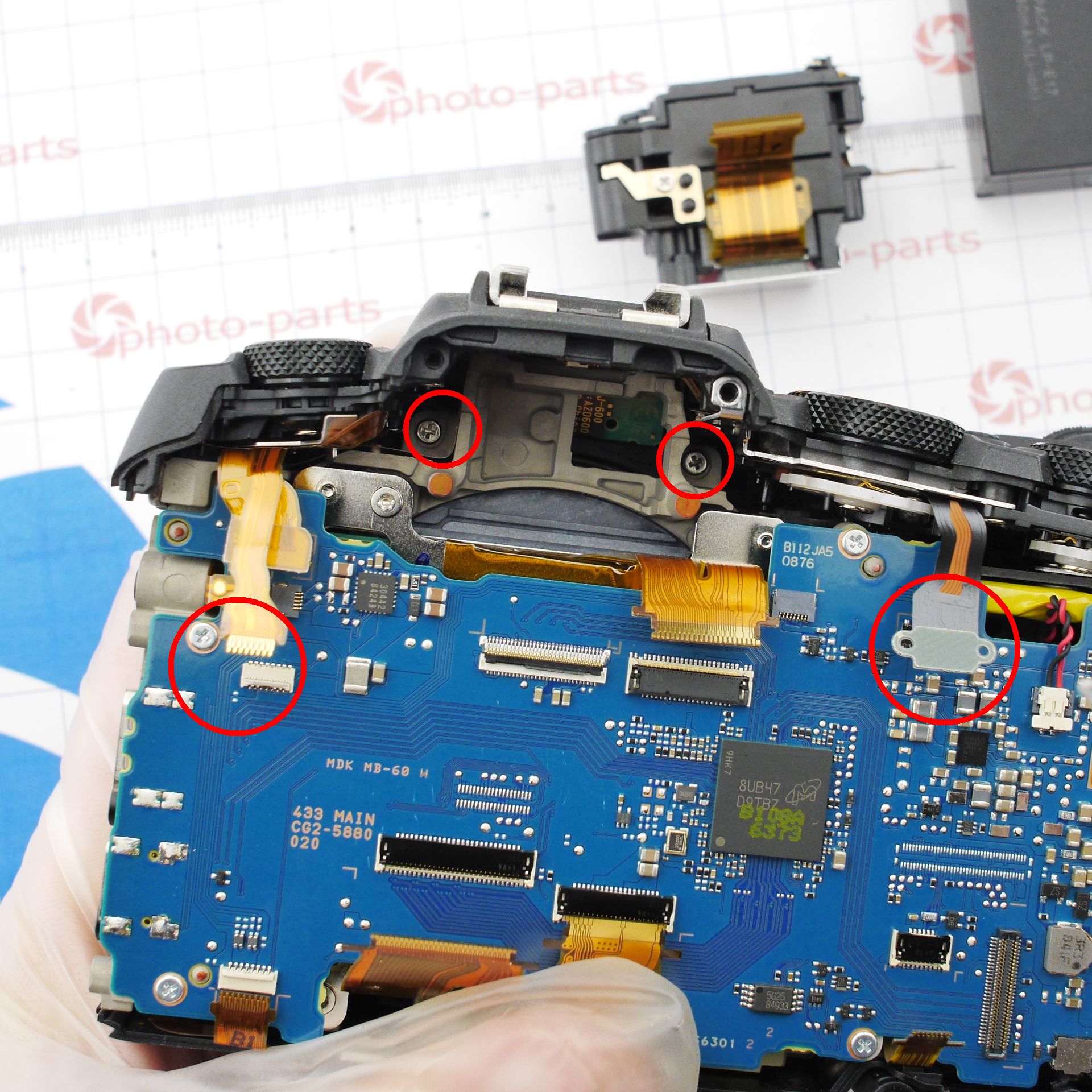
For further disassembly, remove the top cover, which first requires taking out the electronic viewfinder. It's held only by two ribbon cables; once disconnected, it simply slides out.
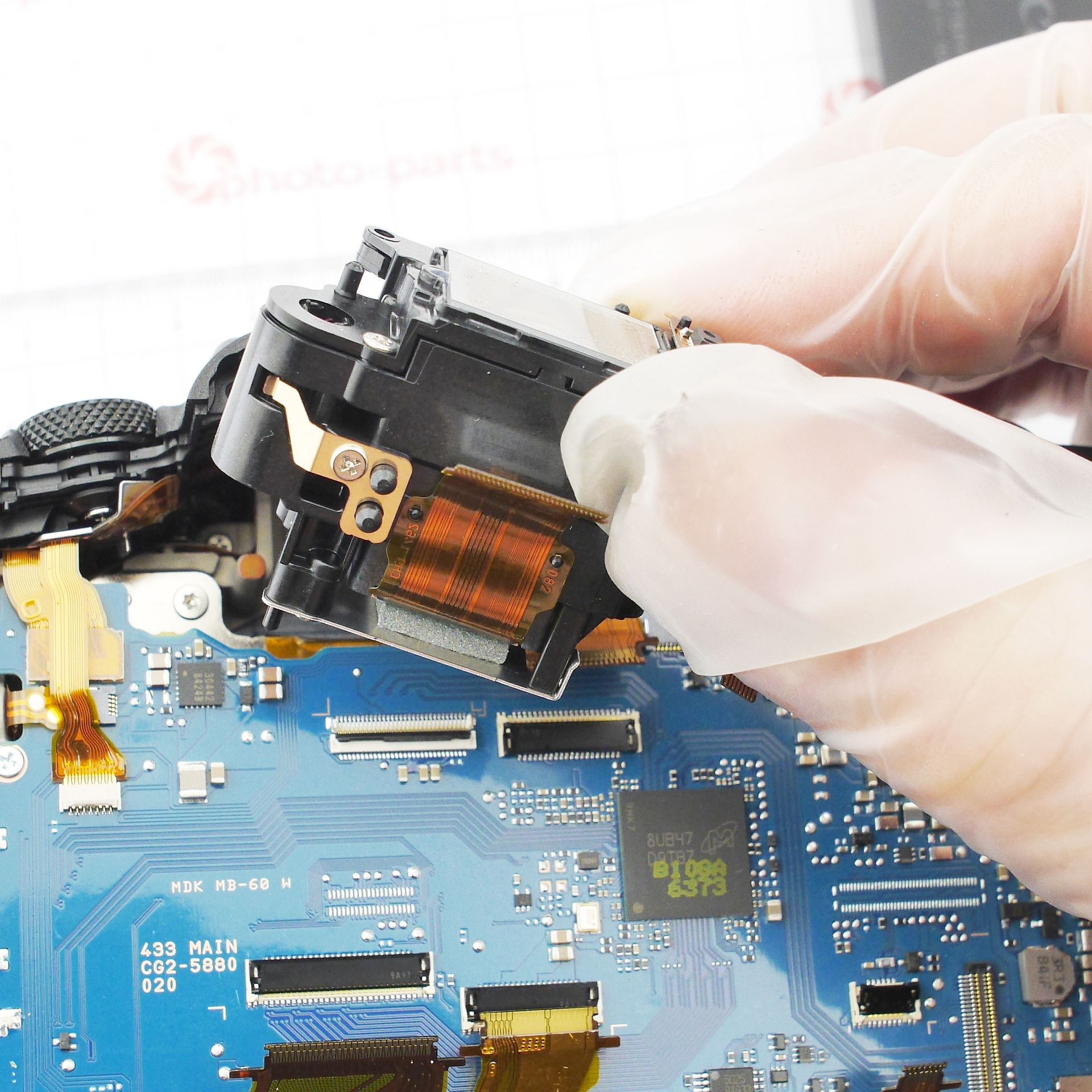
The top panel is secured with four screws: two long ones under the EVF and two near the strap lugs. Don't forget to unplug the two ribbon cables for the top panel.
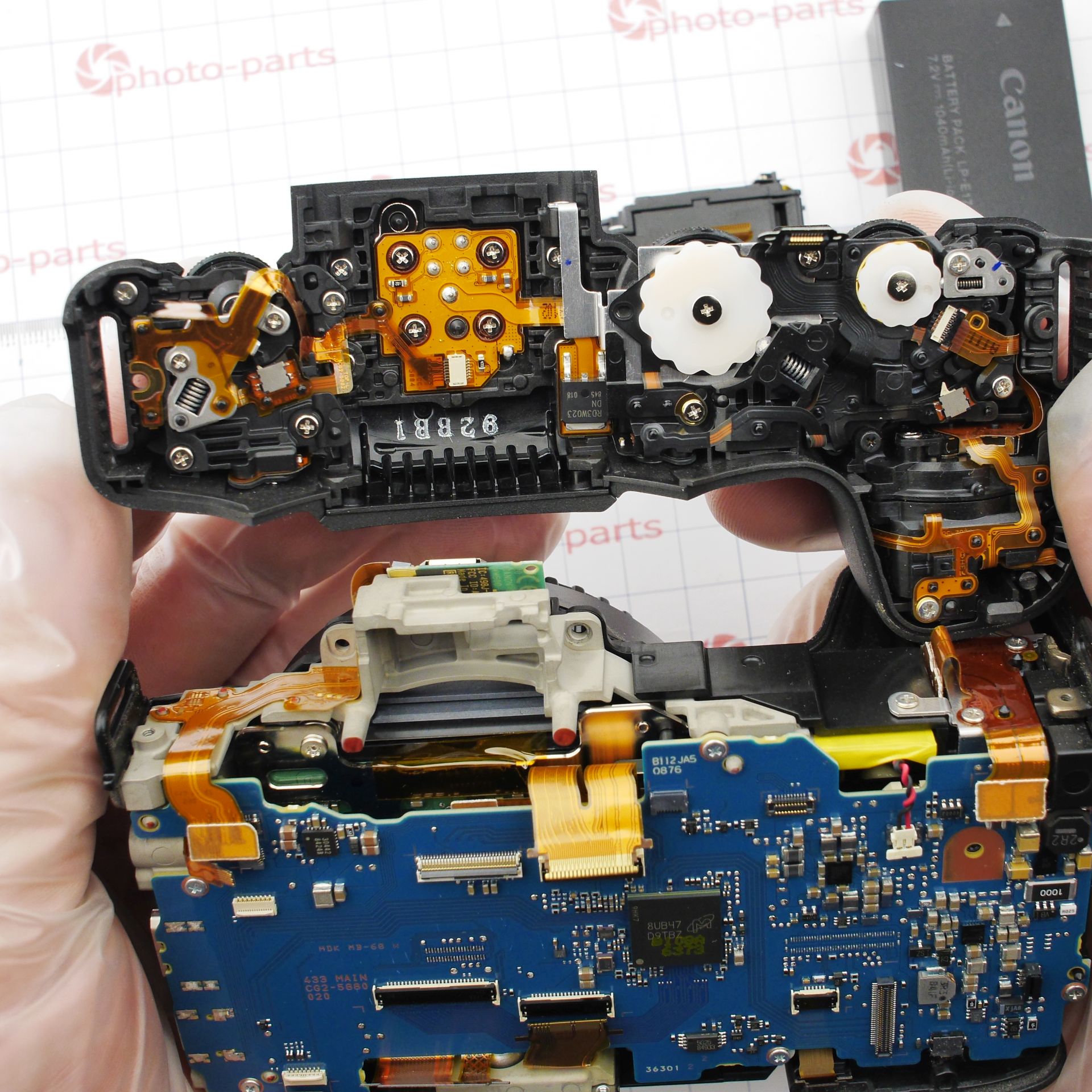
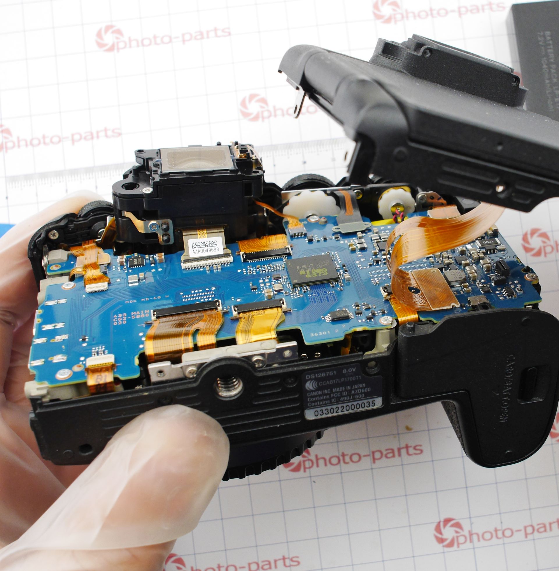
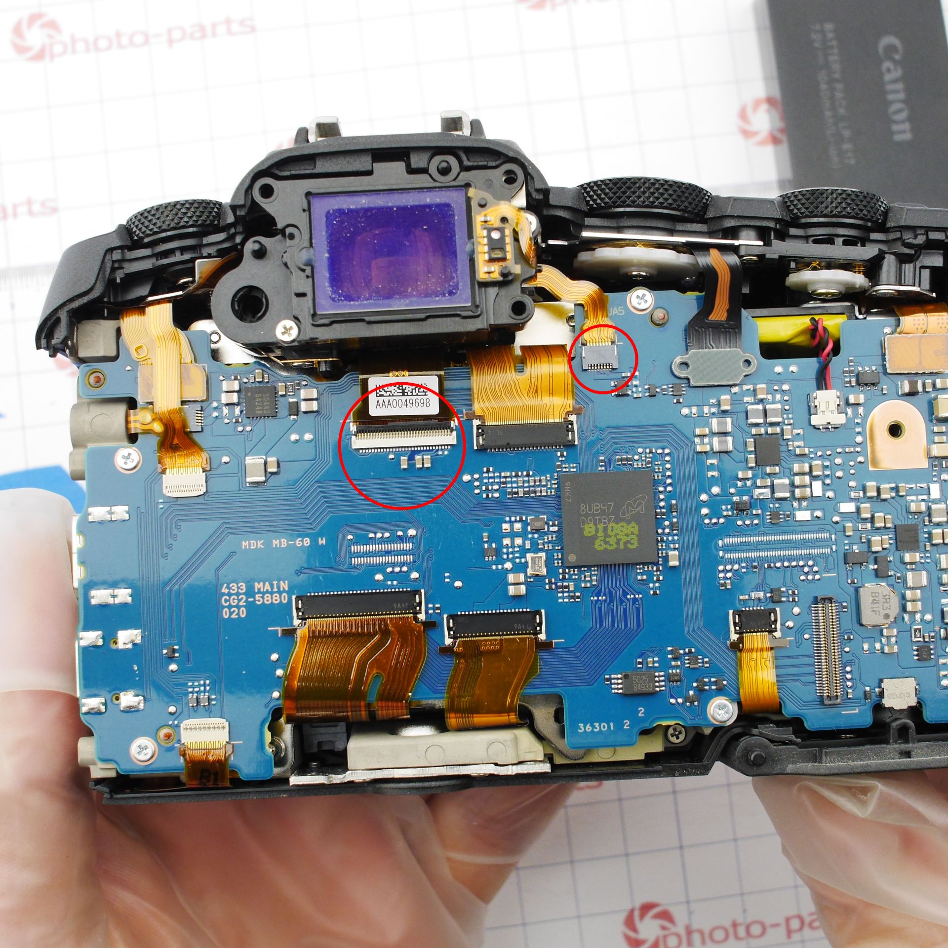
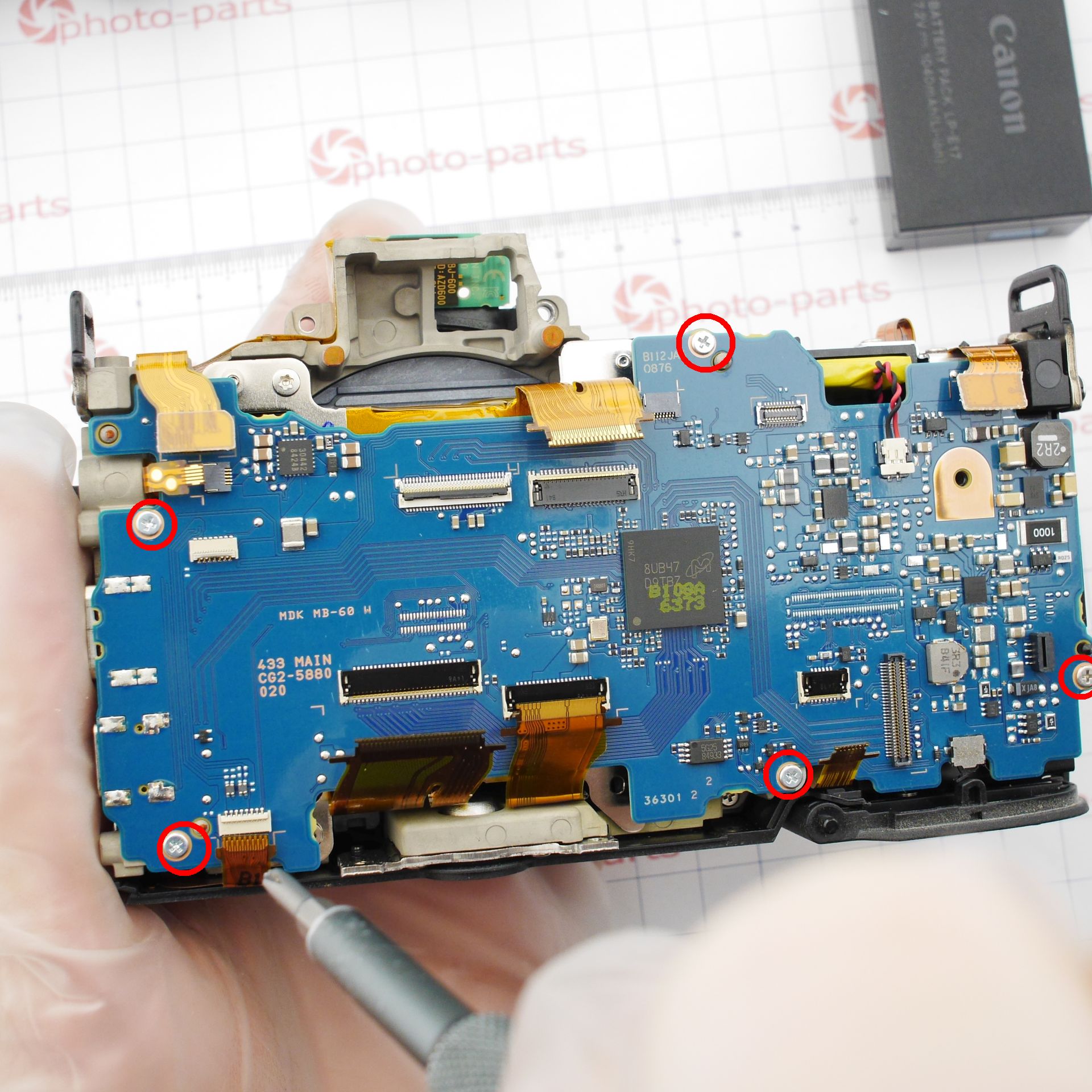
The next step is removing the mainboard. Most connectors here are slightly non-standard - to release the ribbon, the latch must be opened and held at a 90° angle.
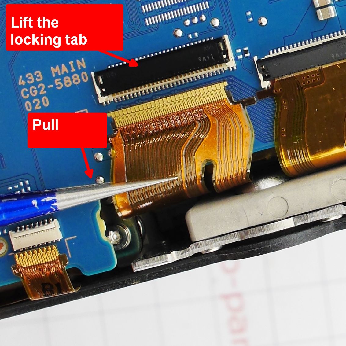
Five screws, nine connectors - and the board is free.
If you want to see the board in full resolution from both sides, here's the top side and bottom side. A list of components and board photos can always be found in our camera database.
Fault Diagnosis
Error 06 can theoretically be caused by only two things - either an electronic failure (the high-frequency voltage isn't being generated) or a fault in the piezo actuator itself, which converts electrical energy into mechanical vibration. In practice, this error is almost always caused by the actuator - the "dust shaker" itself.
Checking it is easy: just measure its capacitance. There's no other way to test it, since it's essentially a capacitor with infinite DC resistance.
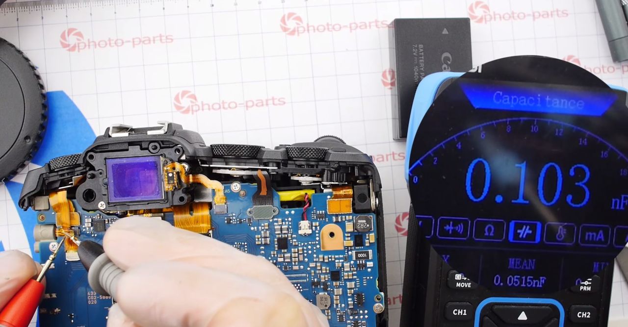
Typical capacitance for this type of actuator is 4–10 nF (4000–10000 pF), but I'm reading only 0.1 nF - 100 pF. Clearly too low, meaning the problem lies in the sensor assembly.
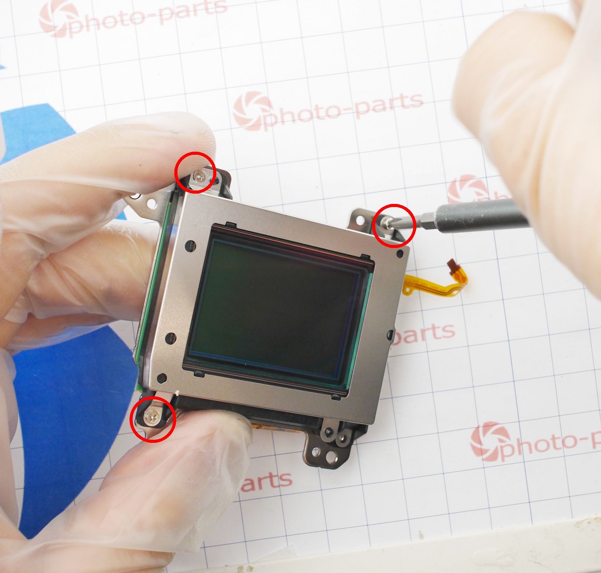
To access the sensor, remove the metal shield:
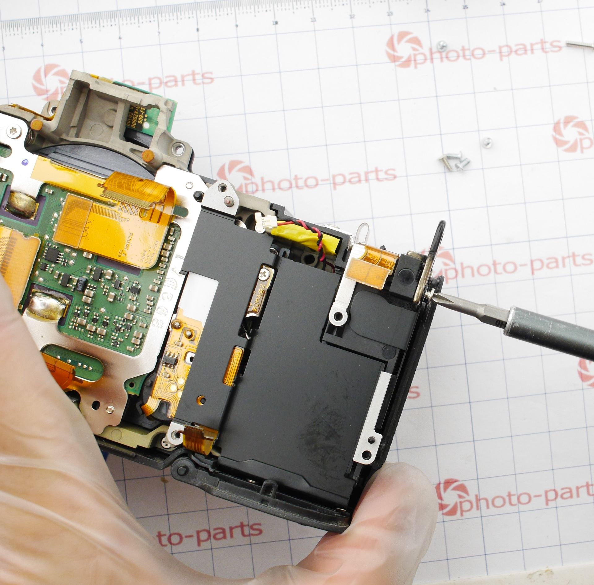
The sensor is mounted on three spring-loaded adjustment screws that define the flange distance, factory-set using precision equipment. The relative adjustment of these screws also defines the sensor's parallelism. Changing this can lead to focus-plane tilt, inconsistent focusing at different focal lengths, or inability to focus to infinity with wide-angle lenses. There's really no way to recalibrate this at home, so the only safe approach is to mark the screws positions before removal.
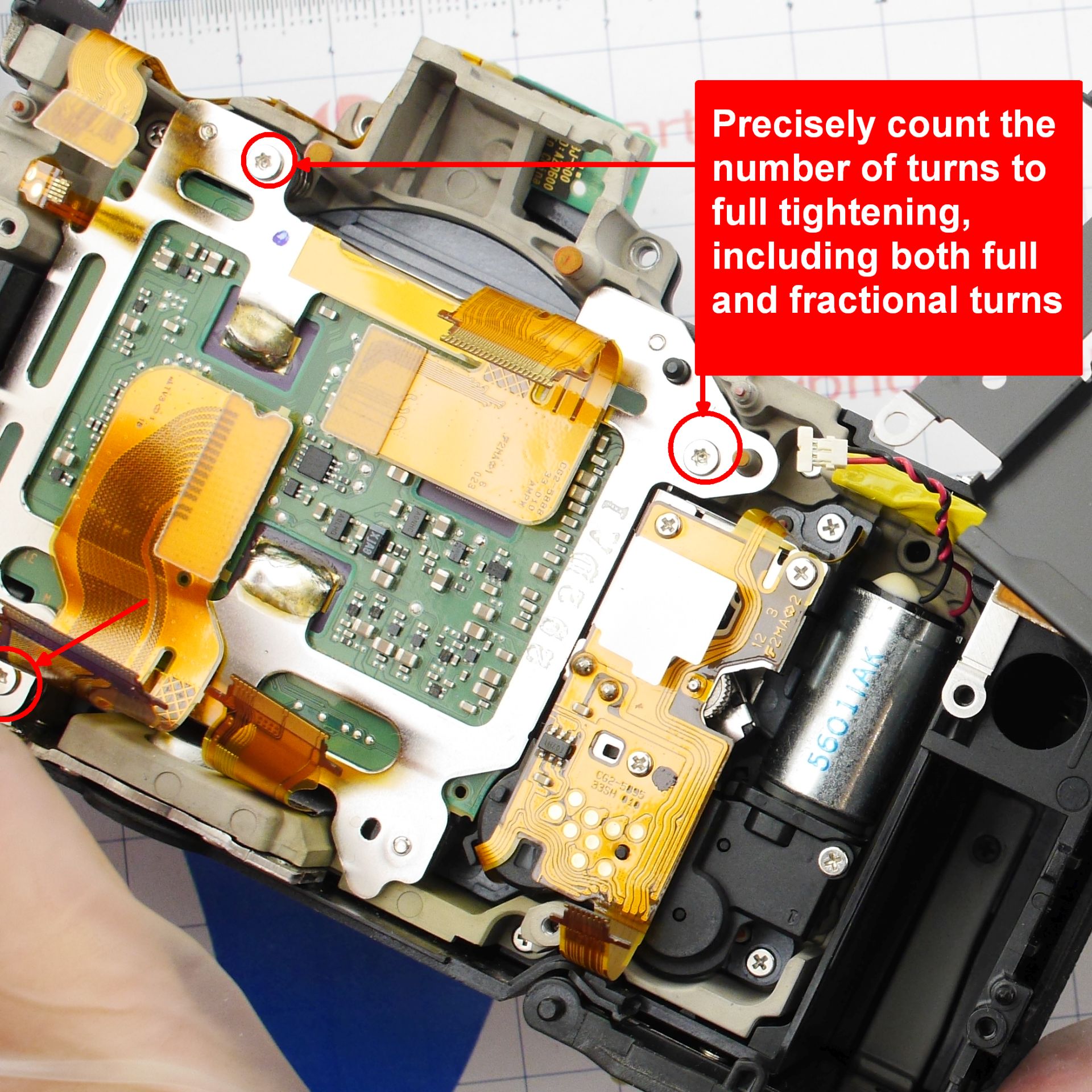
To do that, count the number of turns until fully tightened, accurate to about 10–20 degrees. When reassembling, tighten to the stop, then back off by the same number of turns. In this particular camera, I counted about 0.6–0.8 turns to full tightening (roughly 200–270 degrees). Luckily, the thread pitch is fine enough that an error of half a turn won't noticeably shift the sensor plane. In cameras with plastic mounts and self-tapping screws, the adjustment must be more precise - the pitch is coarser.
If you need access to the shutter, once the sensor is removed, it's held by just three screws. In my case, I only needed the sensor - or rather, the top optical filter layer.
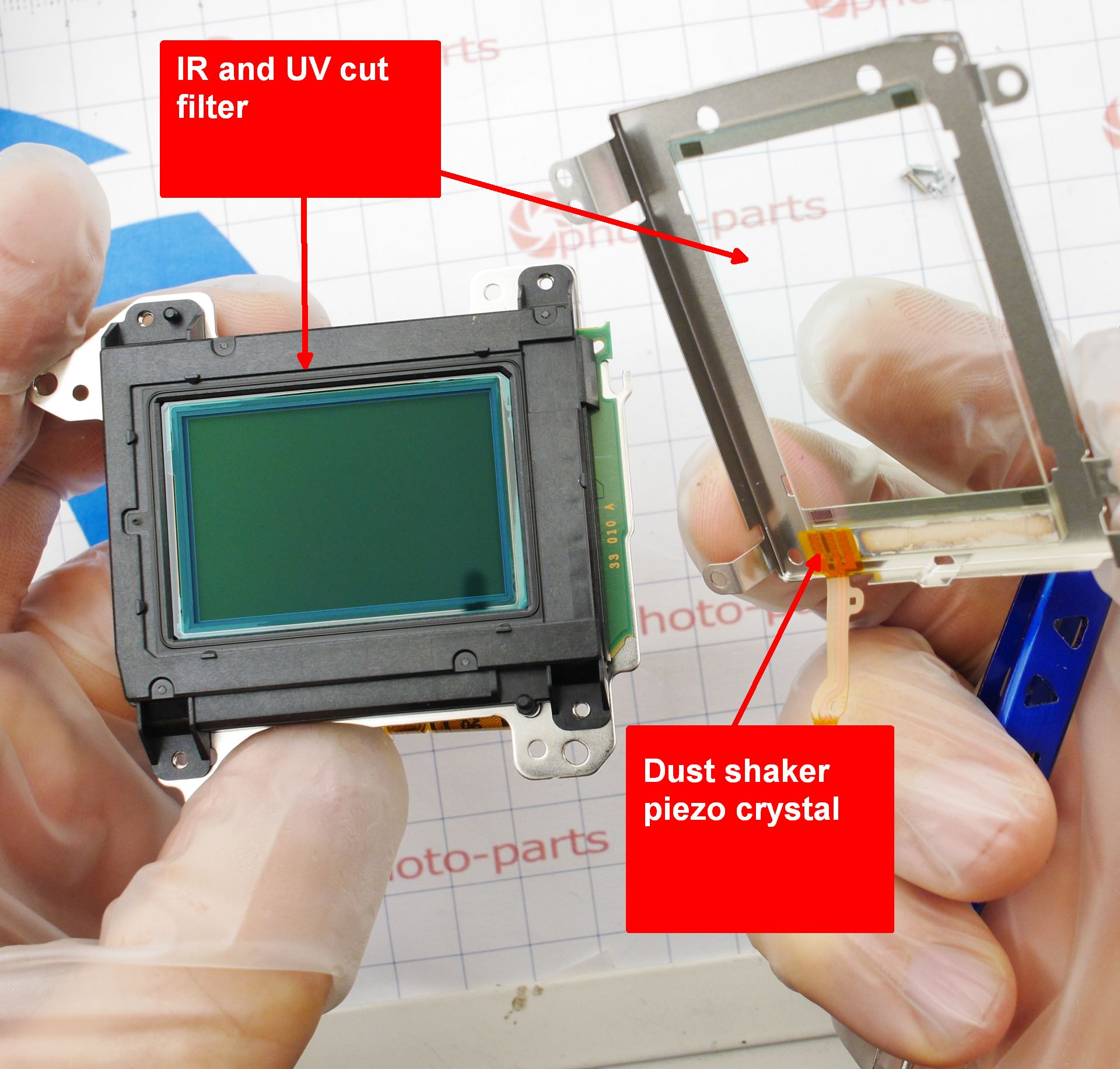
A few geeky facts: the image sensor requires two extra optical elements to function properly - an anti-aliasing (AA) filter and a UV/IR filter.
The role of the IR/UV filter is obvious - the sensor can detect light across a very wide spectrum, extending into ultraviolet and infrared. For normal color photography, that's undesirable, so the filter blocks those parts of the spectrum. This is the one infrared-photography enthusiasts remove - often along with the AA filter, whose function is a bit trickier.
The anti-aliasing filter intentionally softens the image slightly. Why blur something when photographers want razor-sharp? Because of how a color sensor "sees": each pixel consists of four sub-pixels arranged under a Bayer filter. If an image detail is smaller than one filter cell, the color can be misinterpreted. For instance, a white spot focused sharply may land entirely on a blue or red sub-pixel - resulting in a colored pixel instead of white. The AA filter ensures the smallest point of light is large enough to "cover" all sub-pixels of a pixel.
An interesting takeaway: AA filters are tuned individually to each sensor's pixel size. Swapping one from a higher-resolution sensor can introduce aliasing (color moire), while going the other way brings softness.
Fact #2: the outer "dust shaker" glass also doubles as an IR filter - so for full-spectrum conversions, it must be removed as well.
Fact #3: removing all filters makes the camera suitable only for black-and-white photography, due to aliasing - which is, in fact, the usual goal in IR shooting.
The frame with the protective glass/dust shaker comes off easily - four screws and a few clips hold it in place. However, from this point, even a single dust speck can get between the glass layers, forcing a full re-disassembly to blow it out. Be very careful - or better, avoid touching this area altogether.
My trial-and-error journey is shown briefly in the video below:
Under the microscope, pulling slightly on the ribbon revealed a crack in the piezo crystal itself:
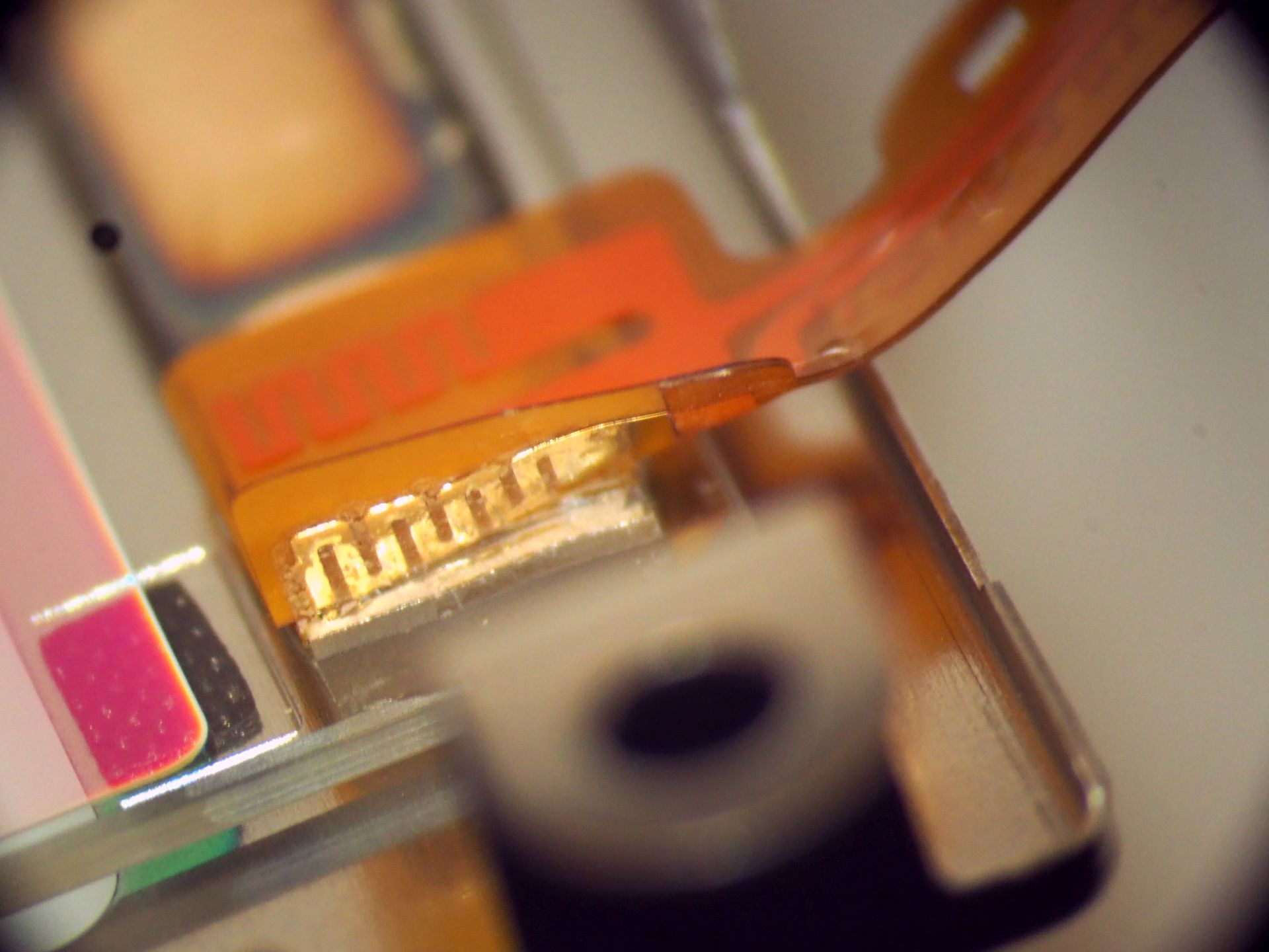
Reaching the metallized layer, I measured a normal actuator capacitance - 6.5 nF.
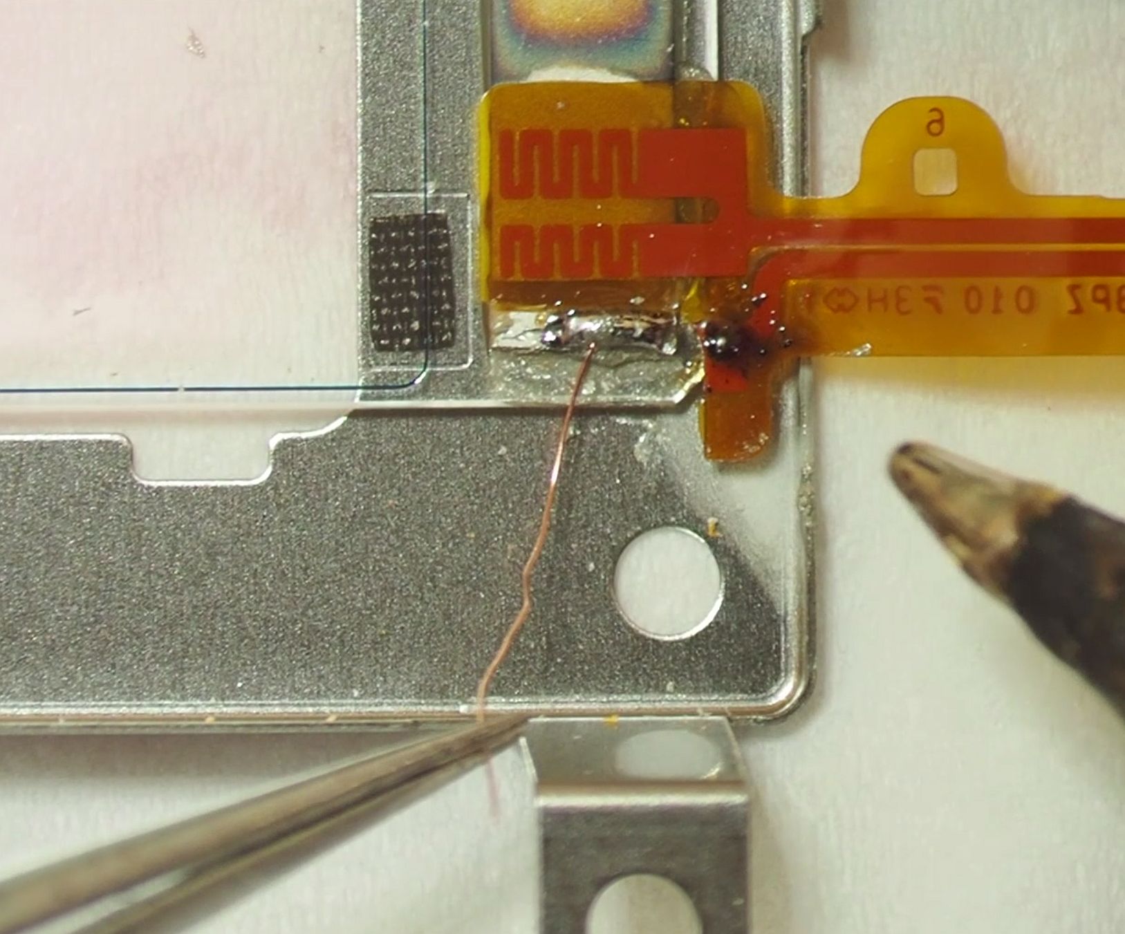
I saw two possible ways to fix it: applying conductive lacquer to the remaining crystal fragment, or soldering a micro-wire directly to the metallization.
I tried both - with no luck. The conductive lacquer never made a stable connection - after the first cleaning cycle, capacitance dropped again.
Soldering seemed like a 100% solution, but it failed too - after a couple of successful cleanings, the contact fell off, and the metallization gave way.
Solution - Fooling the Camera
At this point I faced an unpleasant dilemma: a full repair would mean replacing the entire sensor (the filter isn't available separately) or sourcing a dust-shaker glass from a donor camera - also expensive. The alternative - trick the camera into thinking everything's fine.
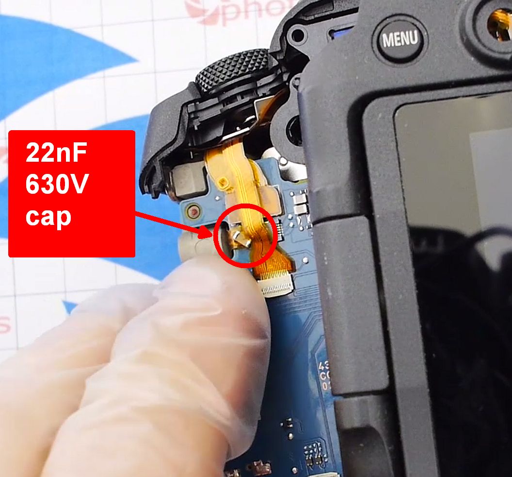
I used a small SMD capacitor, size 0805, rated 22 nF / 630 V, as a "dummy load." Soldered directly across the test pads on the ribbon, and - no more error!
So, even though I didn't restore a fully working camera, the Error 06 problem was solved. The method is a bit like removing the "Check Engine" bulb from a car's dashboard - but the feature I sacrificed was minor. To be fair - cameras of other brands never report cleaning system errors at all, so no one really knows how many dead "dust shakers" are out there.
Happy shooting!
Add Comment
This policy contains information about your privacy. By posting, you are declaring that you understand this policy:
- Your name, rating, website address, town, country, state and comment will be publicly displayed if entered.
- Aside from the data entered into these form fields, other stored data about your comment will include:
- Your IP address (not displayed)
- The time/date of your submission (displayed)
- Your email address will not be shared. It is collected for only two reasons:
- Administrative purposes, should a need to contact you arise.
- To inform you of new comments, should you subscribe to receive notifications.
- A cookie may be set on your computer. This is used to remember your inputs. It will expire by itself.
This policy is subject to change at any time and without notice.
These terms and conditions contain rules about posting comments. By submitting a comment, you are declaring that you agree with these rules:
- Although the administrator will attempt to moderate comments, it is impossible for every comment to have been moderated at any given time.
- You acknowledge that all comments express the views and opinions of the original author and not those of the administrator.
- You agree not to post any material which is knowingly false, obscene, hateful, threatening, harassing or invasive of a person's privacy.
- The administrator has the right to edit, move or remove any comment for any reason and without notice.
Failure to comply with these rules may result in being banned from submitting further comments.
These terms and conditions are subject to change at any time and without notice.
Comments